Micro-fuel co-generation device

A combined heat and power supply and micro-combustion technology, applied in combustion chambers, combustion methods, combustion equipment, etc., can solve the problems of reduced practicability, restraint device performance, and lack of cooking functions, etc., and achieve product cost reduction, energy efficiency improvement, and simple structure Effect

Active Publication Date: 2015-08-19
BEIJING LIANGMING TONGCHUANG WATER TREATMENT EQUIP DEV CENT
View PDF5 Cites 3 Cited by
  • Summary
  • Abstract
  • Description
  • Claims
  • Application Information

AI Technical Summary

Problems solved by technology

[0005] Chinese patent ZL 2011 20318163.6 "Turbine Combustor for Renewable Electric Energy", although it can be fully utilized, it still has the following disadvantages: the structural space of the aviation micro-turbojet engine and the engine turbocharger is small and the interior cannot be equipped with higher power The generator restricts the performance of the device, and the tailpipe of the above-mentioned patent cannot be adjusted and has no cooking function, which reduces the practicability

Method used


Image

  • Micro-fuel co-generation device
  • Micro-fuel co-generation device
  • Micro-fuel co-generation device

Examples


Embodiment 1

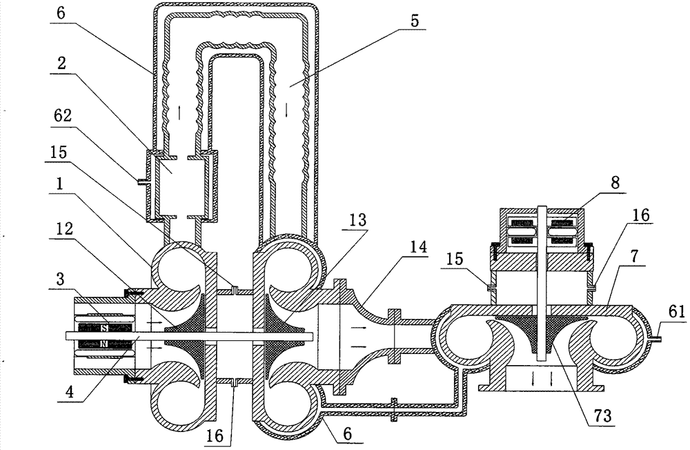
[0038] It can be used in a relatively small or closed space as a heat source and power source, such as a heating power generation device in a tank or an armored vehicle.

[0039] as attached figure 1 Shown, transform on the basis of the turbocharger of existing automobile engine, thus constitute the air compressor and the micro-turbine turbine of this embodiment; Combustion chamber 2 is provided between compressor 1 and micro-gas turbine 13 , the compressor outlet is communicated with the combustor, and the hot gas flow outlet of the combustor is communicated with the micro-turbine turbine inlet through the flame conduit 5, which becomes the turbine combustor of the present embodiment; Another wheel turbocharger is used as the power turbine 7 of the device; generator is installed on the rotating shaft of the power turbine; the hot air outlet of the turbo burner is communicated with the air inlet of the power turbine through the airflow duct 14; the airflow duct It is connecte...

Embodiment 2

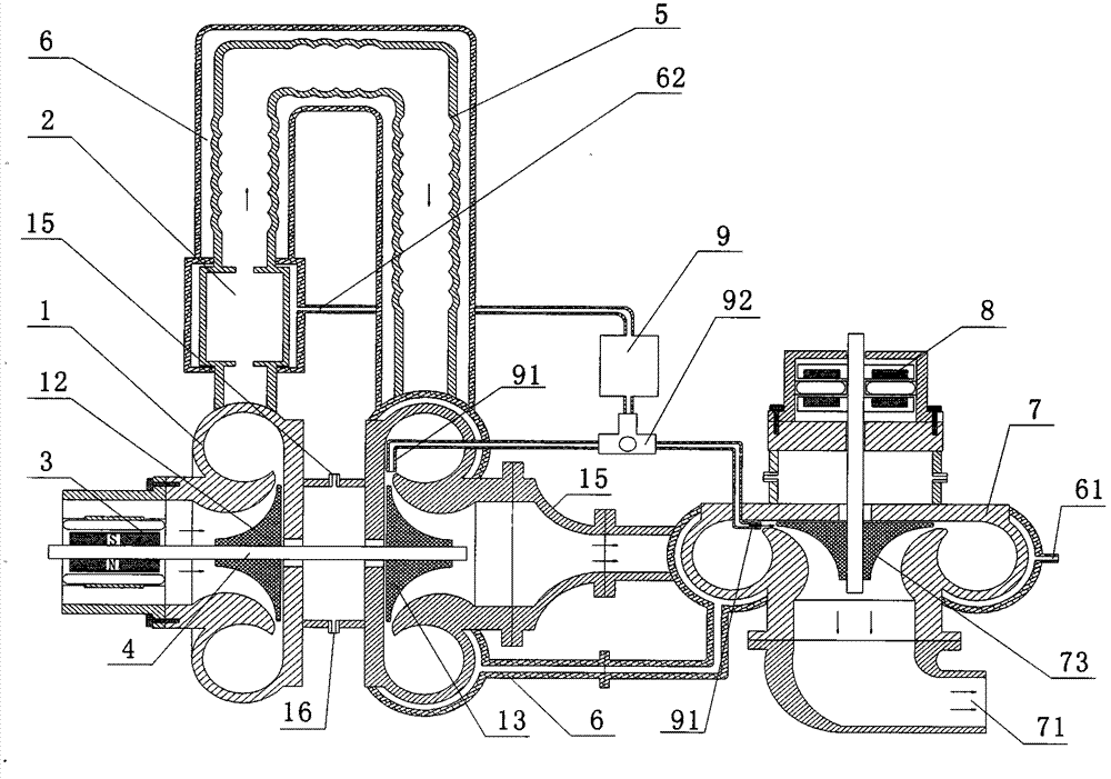
[0048] It is a high-efficiency dual-medium circulation cogeneration device. When working in the field, it can be used as a heat source and power supply, providing heating and power supply, and also serving as a cooking heat source.

[0049] as attached figure 2 As shown, the basic structure is the same as in Embodiment 1.

[0050] The collecting cylinder has the function of collecting and stabilizing the water vapor pressure. The water / steam outlet of the water jacket is connected to the collecting cylinder 9. The air nozzle 91 of the collecting cylinder is set at the tangential angle of the blade of the power turbine and the micro-combustion engine through a two-position three-way valve 92. The tangential angle of the blades of the turbine; the hot steam produced in the water jacket enters the steam collecting cylinder; the hot steam ejected from the air nozzle 91 directly acts on the power turbine 73 and the micro-combustion turbine 13 by using the pressure stabilizing fun...

Embodiment 3

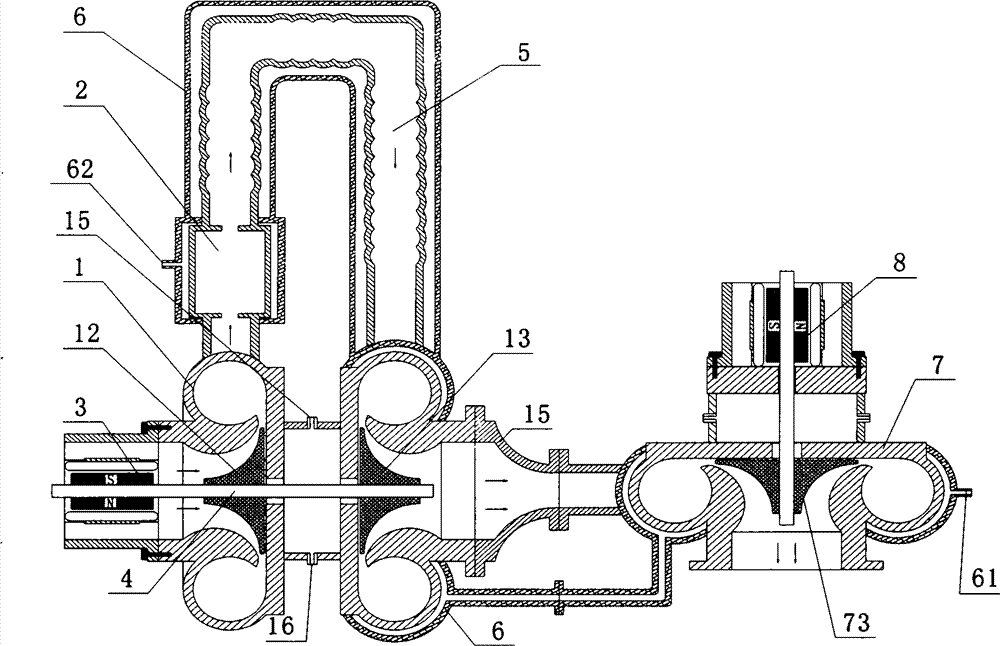
[0056] as attached image 3 As shown, the generator adopts a column motor, and the others are the same as those in Embodiment 1. Further, no power turbine is added, and only a cylindrical water jacket is added to increase the heat exchange area and increase the heat supply.


PUM


Abstract

The invention discloses a micro-fuel co-generation device. By adopting a turbine type burner, a power turbine and an electric motor and using the self-rotation of a burner turbine, a starting generator and a burner hot air driving power turbine drive a generator to provide power source; water sleeves arranged at outsides of a combustor, a flame guide pipe and a volute are connected with a radiator for providing the heating source; a water / gas outlet of each of the water sleeves is interconnected with a gas collecting cylinder, and a nozzle of the gas collecting cylinder is arranged at a tangential angle of a blade of the power turbine; except for the hot air function of the turbine type burner, an assistant power is further provided for the power turbine, double mediums of the hot air and the hot steam are commonly acted on the power turbine to improve the utilization rate of the energy source. The micro-fuel co-generation device can be applied to a relatively narrow or sealed space, such as a warming generating device in a tank or an armored car; the device also can be used as power generating and heating devices at field camp, islands, frontier sentry and the like; when a variable jet nozzle direction is adjusted to vertically upward direction, the device can be applied to kitchen work. Moreover, the micro-fuel co-generation device is simple in structure, low in production cost, and worthy of popularizing.

Description

technical field [0001] The invention relates to an auxiliary energy device for providing power and heat source, in particular a device which uses a turbine burner as a micro-combustion engine and has the functions of power generation and heat supply. Background technique [0002] At present, the burner is composed of an electric fan, a combustion chamber, an igniter, etc. Other oil and gas burners at home and abroad basically consume electricity, but they do not generate electricity themselves. The working electricity must be provided by an external power supply. Among them, the burner fan requires power consumption ranging from several kilowatts to tens of kilowatts, including fans, swirl plates, combustion chambers, igniters, etc. Although the aviation micro-turbojet engine body is exactly a burner, its start mainly adopts a special-purpose starter motor. Because the cost is higher and there are no other functions, it has not been widely used in other fields. [0003] In ...

Claims


Application Information

Patent Timeline
Patent Type & Authority Applications(China)
IPC IPC(8): F01D15/10F23R3/52
Inventor 佟宪良张国梁
Owner BEIJING LIANGMING TONGCHUANG WATER TREATMENT EQUIP DEV CENT
Why Eureka
Try Eureka