
Particle sensor calibration system and measuring method

A particle sensor and calibration system technology, which is applied in the field of vehicle exhaust emission control, can solve the problems of lack of accurate and effective particle sensor calibration devices and measurement methods, and achieve the effect of convenient and reliable recording of instantaneous soot concentration, easy implementation, and reduced energy consumption

Active Publication Date: 2015-08-19
JIANGSU UNIV
View PDF7 Cites 12 Cited by
  • Summary
  • Abstract
  • Description
  • Claims
  • Application Information

AI Technical Summary

Problems solved by technology

However, because the current research on particle sensing technology is not yet mature, many scholars at home and abroad have carried out in-depth research on particle sensors, and proposed various types of particle sensors according to different particle concentration detection principles: resistive, capacitive, electric Chemical formula, catalytic combustion type, and leakage current type all use the electrical signal output by the sensor to determine the carbon content. Now there is a lack of accurate and effective particle sensor calibration devices and measurement methods, and no reports have been seen yet.

Method used


Image

  • Particle sensor calibration system and measuring method
  • Particle sensor calibration system and measuring method

Examples


Embodiment 1

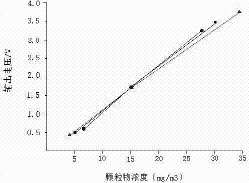
[0019] In the particulate matter sensor calibration system and measurement method of the present invention, the fuel is passed into the back-diffusion flame burner 101, the upper port of the burner is connected with the first lower hole of the exhaust pipe 102, and the mixed gas is ignited to burn to generate stable soot; The compressor 103 blows in a stable amount of air, adjusts the intake air volume through the pressure regulating valve 104, and then heats up through the heater 105, setting the heating rate at 20°C / min until the temperature sensor 107 outputs the final heating temperature to 300°C And maintain, the air after heating enters exhaust pipe and is used for diluting the soot that combustion produces; Regulate pressure regulating valve 104, make the intake flow of flowmeter 106 be 3kg / min; Output the voltage signal after conversion, the signal value is collected by the A / D converter 110, and the voltage value is read out by the computer 111 as 1.7 V, and the s...

Embodiment 2

[0021] On the basis of the method in Example 1, change the heating rate to 10°C / min, and the temperature sensor outputs the final heating temperature to 200°C. When the measured voltage value is 0.4 V, the corresponding particle concentration is 4 mg / m3; change the heating rate to 30°C / min, the temperature sensor outputs the final heating temperature to 400°C, and the corresponding particle concentration is 35 mg / m3 when the measured voltage value is 3.8 V; record the voltage values ​​corresponding to different particle concentrations under the same conditions and change the temperature, and draw Calibration curve 2, a different calibration curve can be obtained, see figure 2 triangular curve.

Embodiment 3

[0023] On the basis of the method in Example 1, under the same circumstances, by adjusting the pressure regulating valve to change different intake flow rates, when the intake flow rate is adjusted to 2kg / min, the corresponding particle concentration when the measured voltage value is 0.6 V is 6mg / min. m3; when the intake air flow rate is adjusted to 4kg / min, the corresponding particle concentration when the measured voltage value is 3.2 V is 28 mg / m3. Record the voltage values ​​corresponding to different particle concentrations by changing the intake flow rate under the same conditions, and draw the calibration curve 3 to obtain another different calibration curve. For details, see figure 2 circular curve.


PUM


Abstract

The invention discloses a particle sensor calibration system and a measuring method. A fuel is introduced into an inverse diffusion flame combustor, an upper combustor mouth is communicated with an exhaust pipe, a gas mixture is ignited, and stable soot is produced by combustion of the gas mixture; a compressor is started, and a stable quantity of air is introduced; air input is adjusted through a pressure-regulating valve, and the air is heated by a heater and then enters the exhaust pipe to dilute the soot produced by combustion; air input flow adjusted by the pressure-regulating valve is read by a flowmeter; a temperature sensor outputs the temperature of diluted particles; the soot enters a particle sensor, a current signal is output and then amplified and converted by a circuit board, then a voltage signal is output, an A / D converter is used to acquire a signal value, and a voltage value is read by a computer; a transient smokemeter is started in the moment when the soot enters the particle sensor, and transient soot concentration is measured and output; and the voltage values output by the particle sensor under different soot concentrations are recorded, a calibration curve representing the changes of the voltage values under different soot concentrations is drafted, and accurate particle concentration is obtained.

Description

technical field [0001] The invention relates to the technical field of vehicle exhaust emission control, in particular to a calibration system and measurement method for a particle sensor. Background technique [0002] It is well known that diesel engine emissions contain a large amount of particulate matter, especially PM 2.5 Accounting for 80% of particulate matter emissions, it will cause great harm to the environment and human health. Therefore, many researchers at home and abroad have carried out in-depth exploration and research on particulate matter emitted by diesel engines. In the United States, the on-board diagnostic regulations have clearly applied for the use of particulate matter The sensor is mainly used to monitor the working condition of the particulate filter (DPF). [0003] At present, California of the United States has formulated the on-board diagnostic system (OBD) emission regulations that will be implemented in 2013, and the particulate matter limit ...

Claims


Application Information

Patent Timeline
IPC IPC(8): G01N15/06
Inventor 汤东朱泽洪王松华王希凡赵岑未建飞
Owner JIANGSU UNIV
Learn More