Voltage-controlled oscillator with low power dissipation, low noise and high linear gain

A voltage-controlled oscillator and low-noise technology, used in power oscillators, automatic power control, electrical components, etc., can solve problems such as inability to meet needs and increase noise, and achieve flicker noise reduction, noise performance improvement, and noise reduction. The effect of small flicker noise

Active Publication Date: 2015-08-19
INST OF ADVANCED TECH UNIV OF SCI & TECH OF CHINA
View PDF6 Cites 17 Cited by
  • Summary
  • Abstract
  • Description
  • Claims
  • Application Information

AI Technical Summary

Problems solved by technology

[0013] Figure 1 to Figure 4 It shows the development direction of VCO. These four methods have their own advantages, but they also have their own shortcomings, which cannot meet the needs.
At present, a tail current source fixed bias VCO that adopts the principle of body bias is commonly used in the market, such as Figure 5 shown in the Figure 1 to Figure 4 Further improvements have been made on the basis of the body bias principle to reduce the threshold voltage of the MOS tube, so that the LC-tank VCO (LC resonant voltage-controlled oscillator) can work at a very low supply voltage and achieve low power consumption, but its noise needs to be improved

Method used


Image

  • Voltage-controlled oscillator with low power dissipation, low noise and high linear gain
  • Voltage-controlled oscillator with low power dissipation, low noise and high linear gain
  • Voltage-controlled oscillator with low power dissipation, low noise and high linear gain

Examples


Embodiment Construction

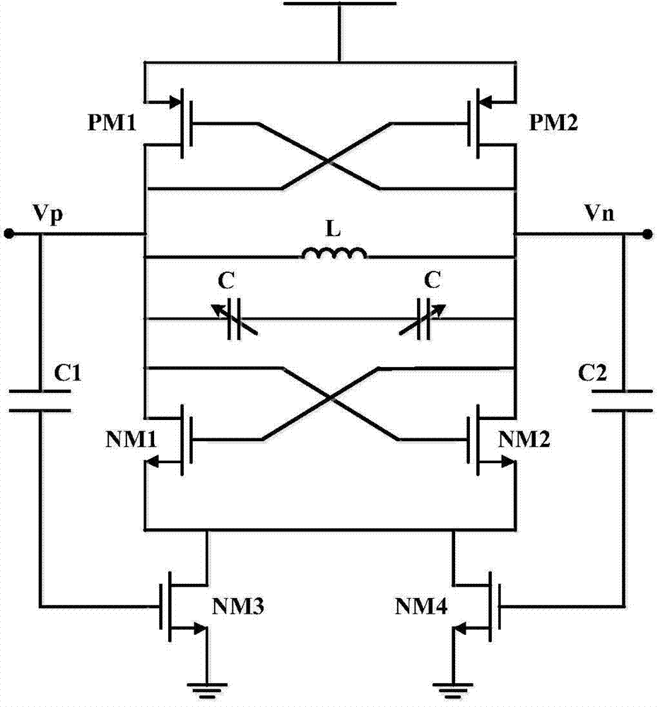
[0043] refer to Image 6 , a voltage-controlled oscillator with low power consumption, low noise and high linear gain proposed by the present invention, which includes: a first inductance L1, a second inductance L2, a distributed varactor structure circuit, a negative resistance differential pair circuit, a tail current Tube circuit and amplitude detection circuit.

[0044] The output terminals of the voltage controlled oscillator include a VCO first voltage output node QP and a VCO second voltage output node QN. One end of the first inductor L1 is connected to the input end of the DC power supply, and the other end is connected to the first voltage output node QP of the VCO; one end of the second inductor L2 is connected to the input end of the DC power supply, and the other end is connected to the second voltage output node QN of the VCO. The distributed varactor structure circuit is connected to the VCO first voltage output node QP and the VCO second voltage output node QN...


PUM


Abstract

The invention discloses a voltage-controlled oscillator with low power dissipation, low noise and high linear gain. The voltage-controlled oscillator comprises a first inductor, a second inductor, a distributed varactor structure circuit, a negative resistance differential pair circuit, a tail current tube circuit and an amplitude detection circuit, wherein the first inductor, the second inductor and the distributed varactor structure circuit are used to form an LC resonance network for generating an oscillating signal of the VCO with low power dissipation, low noise and high linear gain; the negative resistance differential pair circuit is connected with the LC resonance network and is used for providing energy compensation for the LC resonance network; the tail current tube circuit is connected with an output end of the voltage-controlled oscillator, and uses self-biasing to generate a direct current bias voltage to be used as supply voltage for providing direct current for the LC resonance network; the amplitude detection circuit is connected with an output end of the voltage-controlled oscillator for providing bias voltage for the negative resistance differential pair circuit and the tail current tube circuit. The voltage-controlled oscillator of the invention could realize low power dissipation, low noise and high linear gain.

Description

technical field [0001] The invention relates to the technical field of radio frequency integrated circuits, in particular to a voltage-controlled oscillator with low power consumption, low noise and high linear gain. Background technique [0002] At present, a high-speed and stable clock signal is a prerequisite for many applications, such as high-performance analog-to-digital converters, high-speed serial data communications, wireless transceivers, etc. Therefore, for low power consumption, low jitter, high-speed phase-locked The demand for the PLL is increasing day by day, and in the design process of the phase-locked loop, a high-performance VCO (Voltage Controlled Oscillator, voltage-controlled oscillator) is the key. [0003] PLL is the first choice for generating low-jitter and high-frequency clocks. A typical integer-division PLL structure includes five parts: frequency detector, phase detector, charge pump, loop filter, voltage-controlled oscillator, and frequency ...

Claims


Application Information

Patent Timeline
Patent Type & Authority Applications(China)
IPC IPC(8): H03L7/099H03B5/32
Inventor 罗林孟煦林福江
Owner INST OF ADVANCED TECH UNIV OF SCI & TECH OF CHINA
Why Eureka
Try Eureka