Water removal method of dichloromethane
A technology of dichloromethane and water content, applied in separation methods, chemical instruments and methods, liquid separation, etc., can solve the problem of low energy consumption
- Summary
- Abstract
- Description
- Claims
- Application Information
AI Technical Summary
Problems solved by technology
Method used
Image
Examples
Embodiment 1
[0022] Embodiment 1: Carry out dichloromethane dehydration with PTFE membrane
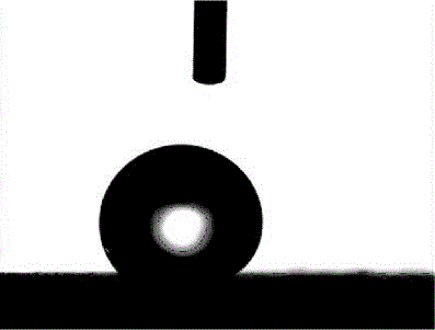
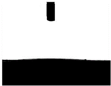
[0023] Take a commercially available PTFE membrane with an average pore size of 0.5 μm, use a contact angle meter to measure the contact angle of water droplets on its surface is 120°, and the contact angle of dichloromethane is less than 5°, cover the PTFE membrane in a porous stainless steel tube to obtain a membrane assembly .
[0024] Take the dichloromethane with a water content of 7% recovered from the film production plant, and filter it with the membrane module equipped with the above-mentioned PTFE membrane. The pressure difference on both sides of the membrane module is 0.1MPa, and the parallel test is performed twice. During the filtration process, the dichloromethane permeated out of the outer wall of the membrane module is collected, and the water content of the permeated dichloromethane measured by a coulometric moisture content meter is less than 0.5%.
Embodiment 2
[0025] Embodiment 2: Carry out dichloromethane dehydration with porous carbon membrane
[0026] Take a commercially available porous carbon film with an average pore diameter of 8 μm, use a contact angle meter to measure the contact angle of water droplets on its surface to be 100°, and the contact angle of dichloromethane to be less than 5°, cover the porous carbon film in a porous stainless steel tube, Obtain the membrane assembly.
[0027] Take dichloromethane with 10% water content for extraction recovered from a pharmaceutical factory, and filter it with the membrane module equipped with the above-mentioned porous carbon membrane. The pressure difference on both sides of the membrane module is 0.1MPa, and the parallel test is performed twice. During the filtration process, the methylene chloride penetrating out of the outer wall of the membrane module is collected, and its water content is lower than 0.5% as measured by a coulometric moisture content analyzer.
Embodiment 3
[0028] Embodiment 3: Carry out dichloromethane dehydration with copper mesh
[0029] Using copper mesh with an average pore size of 18 μm as a support, octadecyltrichlorosilane was coated on the surface of the copper mesh to prepare a hydrophobic and lipophilic mesh. The surface water droplet contact angle measured by a contact angle measuring instrument is 130°, and the dichloromethane contact angle is less than 5°.
[0030] Get the methylene chloride containing 20% water for cleaning recovered from the mechanical processing plant, and filter it with the above-mentioned hydrophobic and lipophilic mesh. The pressure difference on both sides of the membrane is 0.1 Mpa, and the parallel test is performed twice. The dichloromethane permeated through the hydrophobic and lipophilic omentum was collected during the filtration process, and its water content was measured by a coulometric moisture content analyzer to be less than 3%.
PUM
| Property | Measurement | Unit |
|---|---|---|
| Average pore size | aaaaa | aaaaa |
| Average pore size | aaaaa | aaaaa |
Abstract
Description
Claims
Application Information
 - R&D
- Intellectual Property
- Life Sciences
- Materials
- Tech Scout
- Unparalleled Data Quality
- Higher Quality Content
- 60% Fewer Hallucinations
Browse by: Latest US Patents, China's latest patents, Technical Efficacy Thesaurus, Application Domain, Technology Topic, Popular Technical Reports.
© 2025 PatSnap. All rights reserved.Legal|Privacy policy|Modern Slavery Act Transparency Statement|Sitemap|About US| Contact US: help@patsnap.com


