Method and device for controlling crystal orientation in steady-state magnetic field through directional solidification

A technology of directional solidification and crystal orientation, applied in crystal growth, chemical instruments and methods, single crystal growth, etc., can solve problems such as easy growth, and achieve the effect of simple method, convenience and operation

Inactive Publication Date: 2015-08-26
SHANGHAI UNIV
View PDF8 Cites 5 Cited by
  • Summary
  • Abstract
  • Description
  • Claims
  • Application Information

AI Technical Summary

Problems solved by technology

[0003] But sometimes the direction with the best performance is not necessarily the easy growth direction or the easy magnetization direction, and these two methods only complete the texture of a certain crystal direction

Method used


Image

  • Method and device for controlling crystal orientation in steady-state magnetic field through directional solidification
  • Method and device for controlling crystal orientation in steady-state magnetic field through directional solidification
  • Method and device for controlling crystal orientation in steady-state magnetic field through directional solidification

Examples


Embodiment 1

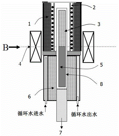
[0021] In this example, see Figure 1 ~ Figure 3 , a directional solidification device, composed of a water-cooled jacket 1, a heating furnace 2, a cooling pool 6, a tie rod 7 and a directional solidification crucible 8, the directional solidification crucible 8 adopts a corundum tube, and corundum has excellent refractoriness and thermal shock resistance, The directional solidification crucible 8 with the metal rod placed inside is set in the heating furnace 2, and the outer side of the heating furnace 2 is equipped with a water-cooled jacket 1, and a temperature control device is provided to control the temperature of the heating furnace 2. The pull rod 7 and the directional solidification crucible 8 Connected, the cooling pool 6 is located below the heating furnace 2, and a magnet 4 is also provided on the outside of the water-cooled jacket 1. The magnet 4 adopts a superconducting strong magnet, and the magnetic field direction of the stable magnetic field generated by the m...

Embodiment 2

[0029] This embodiment is basically the same as Embodiment 1, especially in that:

[0030] In this example, see figure 2 , a method for directional solidification to control crystal orientation under a steady magnetic field, the specific implementation steps are as follows:

[0031] a. This step is identical with embodiment one;

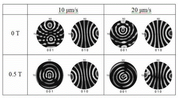
[0032] b. Put the vertical directional solidification device into the electromagnet that can generate a horizontal magnetic field, connect the corundum tube to the pull rod of the directional solidification device, so that it can be pulled in the heating furnace for vertical movement; turn on the electromagnet to generate 0.5 T Transverse magnetic field, heat to 900°C to melt the alloy and keep it warm for 0.5 hours, then turn on the drawing system to perform directional drawing at a set pulling speed of 20 μm / s, and ensure that the solid-liquid interface is in a stable magnetic field area during the drawing process; After the drawing is completed, ...


PUM

PropertyMeasurementUnit
diameteraaaaaaaaaa
lengthaaaaaaaaaa

Abstract

The invention discloses a method and a device for controlling crystal orientation in a steady-state magnetic field through directional solidification. Metal containing anisotropic crystals and alloys are put in a directional solidification device in the steady-state magnetic field; for a certain crystal with a difference in easy growth direction and easy magnetization direction, the steady-state magnetic field and direction solidification are adopted, so that textures can be formed in the easy growth direction and easy magnetization direction respectively, that is, when the easy growth direction of the crystal is orientated in the direction opposite to heat flux in the directional solidification process, the steady-state magnetic field is applied at a certain angle in the directional solidification process according to characteristics of crystallography, accordingly, the easy magnetization direction can turn to a magnetic field direction, and the purpose that multiple crystals form multi-crystal-orientation textures is achieved. The method is simple and convenient to operate.

Description

technical field [0001] The invention relates to a metal material solidification process and device, in particular to a metal directional solidification method and device, which are applied in the technical field of metal material solidification structure control. Background technique [0002] Crystals are often anisotropic, and their mechanical, electromagnetic, optical, corrosion resistance, magnetism and even nuclear physics properties will show significant differences in different crystallographic directions, so the most excellent performance. Many metal materials are polycrystalline. If the crystal orientation with the best performance forms a texture, the performance of the material will be greatly improved. Directional solidification is a good means of controlling crystal orientation. Its characteristic is that a temperature gradient in a specific direction is established in the metal solid phase and liquid phase, so that the melt solidifies along the direction oppos...

Claims


Application Information

Patent Timeline
Patent Type & Authority Applications(China)
IPC IPC(8): C30B28/06C30B29/52
Inventor 李喜李寒骁杜大帆关光张雷
Owner SHANGHAI UNIV
Why Eureka
Try Eureka