
A Calculation Method for Optimal Spacing of Cooling Pipes on the Backside of Mirror Body in Extreme Ultraviolet Collection System

A collection system and cooling pipeline technology, applied in special data processing applications, instruments, electrical digital data processing, etc., can solve problems such as the reduction of the life of the mirror substrate and the film layer, the impact of the system life and performance, and the poor quality of the lithography chip.

Active Publication Date: 2018-05-08
HARBIN INST OF TECH
View PDF4 Cites 0 Cited by
  • Summary
  • Abstract
  • Description
  • Claims
  • Application Information

AI Technical Summary

Problems solved by technology

[0003] However, in the initial stage of the development of extreme ultraviolet lithography technology, the research and development work only focused on the improvement of the power of the light source, but did not pay attention to the problem of high heat introduction caused by the high-power light source under the working state of the system, and the high temperature caused by strong radiation has great impact on subsequent System life and performance impact is fatal
[0004] For the extreme ultraviolet collection system, if the absorbed high heat cannot be released in a timely and effective manner, the temperature of the mirror substrate will rise sharply within tens of seconds. On the one hand, it will cause thermal deformation of the mirror body of the collection system, resulting in The light rays cannot be effectively converged at the intermediate focal point, so that the collection efficiency of the collection system is greatly reduced, the light spot at the intermediate focal point will also be seriously deformed, and the energy distribution will be uneven, which is extremely unfavorable to the subsequent lighting system and exposure system. As a result, the quality of the lithography chip is poor, the output is low, and it cannot meet the requirements; on the other hand, the mirror absorbs high heat and causes a sharp rise in temperature, which seriously reduces the life of the mirror substrate and the film layer.

Method used


Image

  • A Calculation Method for Optimal Spacing of Cooling Pipes on the Backside of Mirror Body in Extreme Ultraviolet Collection System
  • A Calculation Method for Optimal Spacing of Cooling Pipes on the Backside of Mirror Body in Extreme Ultraviolet Collection System
  • A Calculation Method for Optimal Spacing of Cooling Pipes on the Backside of Mirror Body in Extreme Ultraviolet Collection System

Examples


Embodiment Construction

[0052] The technical solution of the present invention will be further described below in conjunction with the accompanying drawings, but it is not limited thereto. Any modification or equivalent replacement of the technical solution of the present invention without departing from the spirit and scope of the technical solution of the present invention should be covered by the present invention. within the scope of protection.

[0053] In the extreme ultraviolet light source collection system, for a given light source and a single-layer mirror body, the total heat flux density of the mirror surface is:

[0054] Hyperboloid part: fz(x)=3557*exp(-0.02009*x)-814.7*exp(-0.2342*x);

[0055] Ellipsoid part: fz(x)=0.00687*x.^3-2.149*x.^2+217.8*x-5381;

[0056] (The origin of the equation is the intersection point of the axis of the mirror body and the front face of the mirror body)

[0057] The inner diameter of the cooling water pipe is 5mm, and the outer diameter is 8mm; the flow ...


PUM


Abstract

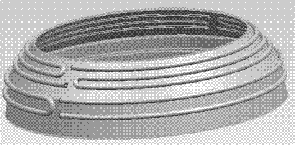
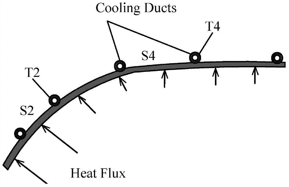
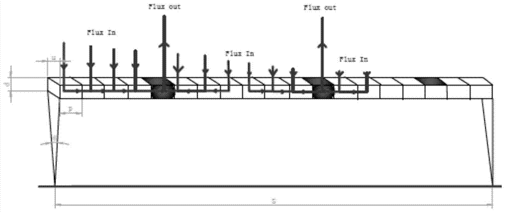
The invention discloses a method for calculating the optimal spacing of the cooling pipes on the back side of the mirror body in an extreme ultraviolet collection system. The steps are as follows: S1: According to the heat flux distribution characteristics of the mirror body, preliminarily determine the overall arrangement and layout of the cooling pipes on the back side of the mirror body Scheme; S2: Establish a heat transfer physical model that can reflect the actual situation; S3: Establish a numerical calculation model for heat transfer between the mirror body and the cooling pipe, and initially obtain the temperature distribution of the mirror body along the axial direction; S4: Consider water flow heat absorption Due to the temperature difference of the tube wall caused by the temperature rise, a set of energy conservation relational formula is added to the calculation, and the more accurate mirror body temperature is solved again; S5: Based on the technical scheme steps of S1, S2, S3, and S4, the optimal spacing of the cooling tubes is optimized The program, and the spacing of each single tube as the last loop variable is added to the program operation to obtain the optimal solution for the spacing of adjacent single tubes. The present invention can accurately calculate the optimal solution of the spacing of the cooling pipes, so that the entire mirror body in the extreme ultraviolet collection system can achieve a uniform and stable temperature distribution, thereby accurately and optimally designing the arrangement and layout of the cooling pipes.

Description

technical field [0001] The invention relates to a method for calculating the optimum spacing for the arrangement and layout of the cooling pipes of the reflection mirror body of the extreme ultraviolet collection system in extreme ultraviolet lithography. Background technique [0002] Near-extreme ultraviolet lithography (EUVL) is considered to be one of the most promising lithography technologies in the next generation. In recent years, several foreign extreme ultraviolet lithography research and development institutions have made some breakthroughs, such as the gradual and steady increase in the power of the light source, the continuous optimization of the design of the collection system, lighting system, and projection system, and the mask The preparation process of the plate and photoresist is continuously improved. [0003] However, in the initial stage of the development of extreme ultraviolet lithography technology, the research and development work only focused on t...

Claims


Application Information

Patent Timeline
Patent Type & Authority Patents(China)
IPC IPC(8): G06F17/50
Inventor 王安妮张树青
Owner HARBIN INST OF TECH
Learn More