Miniature ultrahigh frequency anti-metal multipurpose RFID label antenna

An RFID tag, anti-metal technology, applied in the direction of antenna support/installation device, radiating element structure, etc., can solve the problems of easy damage, poor performance, inconvenience, etc., and achieve flexible adjustment ability, good working performance, and expansion The effect of working range

Active Publication Date: 2015-08-26
SHANGHAI UNIV
View PDF6 Cites 4 Cited by
  • Summary
  • Abstract
  • Description
  • Claims
  • Application Information

AI Technical Summary

Problems solved by technology

Excessive antenna size brings inconvenience to use, and is also easy to damage
Another weakness of existing anti-m

Method used


Image

  • Miniature ultrahigh frequency anti-metal multipurpose RFID label antenna
  • Miniature ultrahigh frequency anti-metal multipurpose RFID label antenna
  • Miniature ultrahigh frequency anti-metal multipurpose RFID label antenna

Examples


Embodiment 1

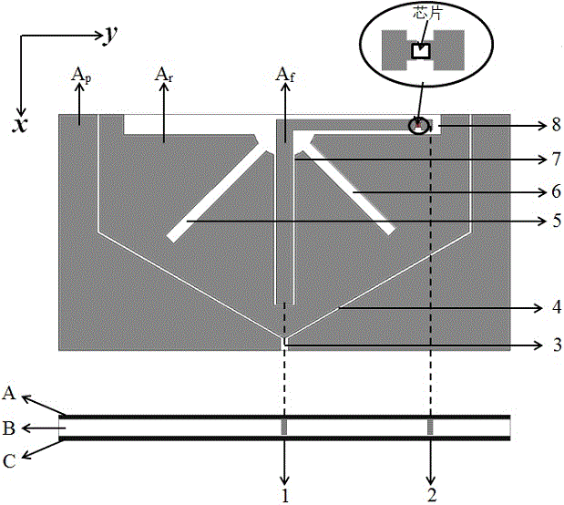
[0031] see figure 1 , The miniaturized ultra-high frequency anti-metal multi-purpose RFID tag antenna includes three layers of metal patch A, dielectric material B and metal film C from top to bottom. The metal patch A contains the main radiation patch A r , parasitic patch A p , L-type feeder A f and other structures. It is characterized by:

[0032] 1) The L-shaped feeder A f It is a non-equal-width L-shaped feeder that is wider in the longitudinal direction than in the transverse direction, and its longitudinal and transverse ends are respectively grounded through short-circuit pin 1 and short-circuit pin 2, and a label chip is connected to the transverse end;

[0033] 2) The main radiation patch A r Presents the outline of half a regular hexagon, the main radiation patch A r outside is the parasitic patch A p , parasitic patch A p and main radiation patch A r There is a gap between 4, parasitic patch A p There is a gap 3 at the middle end;

[0034] 3) The main ...

Embodiment 2

[0038] This embodiment is basically the same as Embodiment 1, and the special features are as follows:

[0039] 1) The main radiation patch A r and parasitic patch A p is fully enclosed;

[0040] 2) The size of the dielectric material B is larger than that of the metal patch A;

[0041] 3) When used on the surface of metal products, the metal film C may not be present.

Embodiment 3

[0043] This embodiment is basically the same as Embodiment 1, and the special feature is as follows: the working performance of the antenna on the surface of five common materials, namely dry wood, paper, hard rubber, quartz glass and porcelain products, and other non-metallic products.

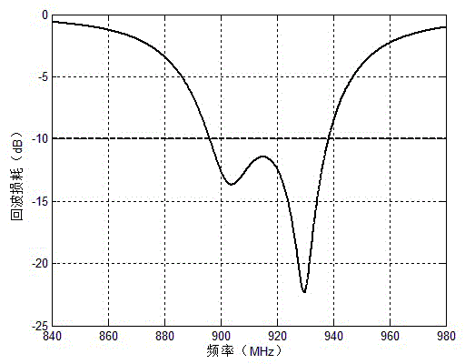
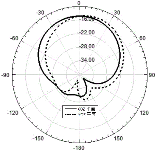
[0044] Figure 5~7 Performance parameters of the antenna on the surface of the above article are shown. Figure 5 The return loss parameters of the antenna on the above material items are shown, Image 6 with Figure 7 The antenna pattern at 910MHz and 920MHz are shown respectively. Antenna gain increases with the increase of material permittivity. Within the range of the dielectric constant of the above materials (ε r=2~4), the main axis gains of the antenna at 910MHz and 920MHz are -17~-13dBi and -13~-11dBi respectively. The antenna can meet the return loss requirements of the 902MHz~928MHz band when placed on the above-mentioned material items, and the pattern shows that the antenna h...


PUM


Abstract

The invention relates to a miniature ultrahigh frequency anti-metal multipurpose RFID label antenna. The label antenna is composed of a slotted metal sheet layer, a medium material layer and a metal film layer. The label antenna has a low profile, the area of the surface of the label antenna is only 15 cm<2>, and the label antenna meets requirements of ultrahigh frequency RFID wave bands, ranging from 902MHz to 928MHz under a -10dB condition, in South America, North America, China and Australia. The label antenna has good working performance when used on the surfaces of metal and nonmetal products. The label antenna can be widely applied to logistics management, production management, warehousing and transportation, and the like.

Description

technical field [0001] The invention relates to a miniaturized ultra-high frequency anti-metal multipurpose RFID (radio frequency identification) tag antenna. Background technique [0002] With the continuous increase of application requirements such as logistics transportation and warehouse management, ultra-high frequency radio frequency identification (UHF-RFID) technology has received more and more attention in recent years. In many application areas, labels need to be attached to the surface of metal products. Because the metal surface will affect the performance of the tag antenna, it will encounter great challenges when applying radio frequency identification technology to items containing a lot of metal, such as all metal products, antiques, banknotes, and vehicles. [0003] Some anti-metal RFID tag antennas currently proposed are relatively large in size, and the general dielectric layer area is not less than 70×70mm 2 , and the area of ​​the metal patch part is n...

Claims


Application Information

Patent Timeline
IPC IPC(8): H01Q1/38H01Q1/22
Inventor 沈文辉林嘉宏
Owner SHANGHAI UNIV
Why Eureka
Try Eureka