A circuit and method for detecting received optical signal strength in a wide dynamic range

A technology with wide dynamic range and signal strength, which is applied in measuring circuits and using electric radiation detectors for photometry, etc., can solve problems such as higher working accuracy requirements, smaller VROP minimum value, difficult circuit design, etc., to achieve high detection The effect of precision and ease of use

Active Publication Date: 2017-01-04
FENGHUO COMM SCI & TECH CO LTD +1
View PDF5 Cites 0 Cited by
  • Summary
  • Abstract
  • Description
  • Claims
  • Application Information

AI Technical Summary

Problems solved by technology

[0005] (1) The operating voltage with a wide range is difficult to design and use for subsequent voltage-type comparator circuits
[0006] (2) Subsequent voltage-type comparator circuit design and integrated circuit manufacturing process are difficult to guarantee the working accuracy of 4mV and below, which makes it difficult to carry out later work
[0007] At the same time, if the resistance value of R1 is reduced, although the range of VROP will be narrowed, the minimum value of VROP will also be reduced, which in turn requires higher working precision and is difficult to meet the needs of equipment.

Method used


Image

  • A circuit and method for detecting received optical signal strength in a wide dynamic range
  • A circuit and method for detecting received optical signal strength in a wide dynamic range

Examples


Embodiment Construction

[0029] The present invention will be described in further detail below in conjunction with the accompanying drawings and embodiments.

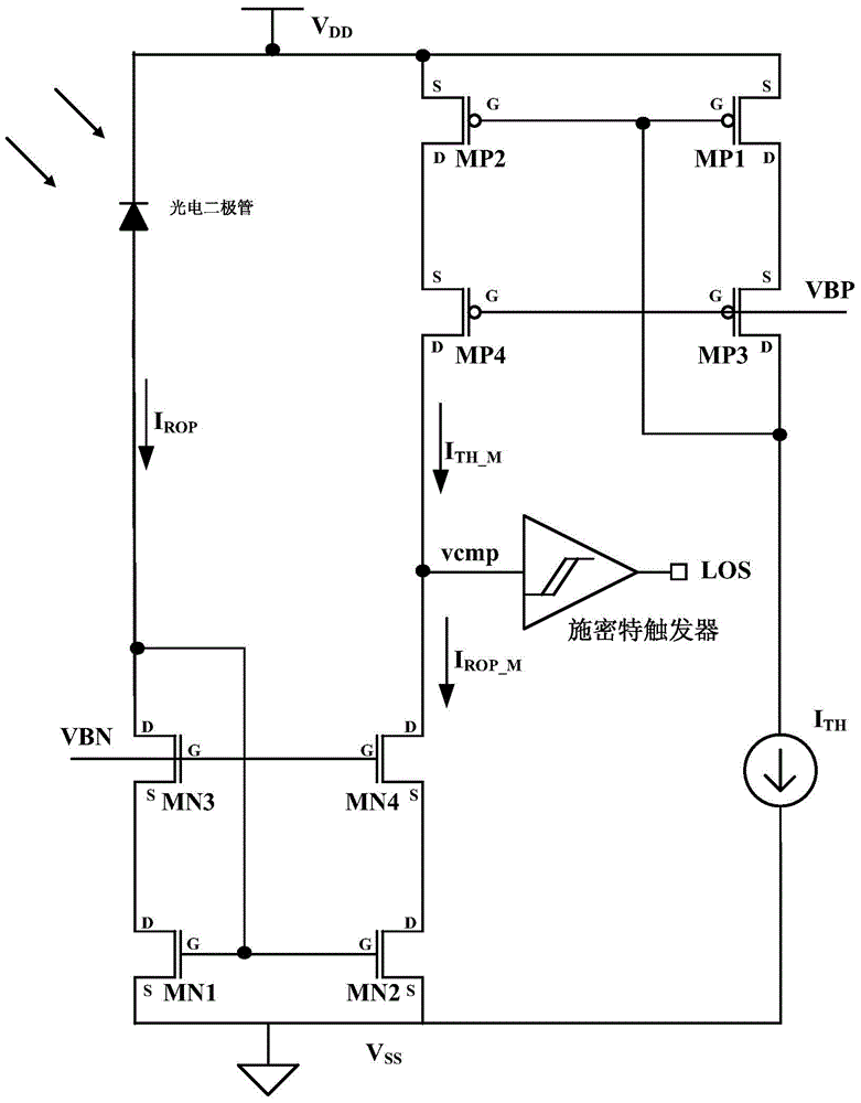
[0030] The circuit for detecting the intensity of received optical signals in a wide dynamic range in the embodiment of the present invention includes a power supply VDD, a photodiode, a buffer (the buffer in this embodiment uses a Schmitt trigger), a threshold current source, and 4 NMOS (N-Mental-Oxide-Semiconductor, N-type Metal-Oxide-Semiconductor Field Effect) transistors composed of cascode photocurrent mirrors, 4 PMOS transistors (positive channel Metal Oxide Semiconductor, n-type substrate, p-channel , a threshold current mirror of a cascode structure composed of a MOS transistor that carries current through the flow of holes).

[0031] see figure 2 As shown, the power supply VDD is connected to the cathode of the photodiode, the anode of the photodiode is connected to the input terminal of the photocurrent mirror, and the output term...


PUM


Abstract

The invention discloses a circuit and a method for detecting the intensity of received light signals in a wide dynamic range, and relates to the field of optical communication integrated circuit design. The circuit includes a power supply, a photodiode, a buffer, a threshold current source, a photocurrent mirror of a cascode structure composed of 4 NMOS transistors, and a threshold current mirror of a cascode structure composed of 4 PMOS transistors; the power supply and photoelectric The cathode of the diode is connected, the anode of the photodiode is connected with the input terminal of the photocurrent mirror, and the output terminal of the photocurrent mirror is grounded; the power supply is also connected with the input terminal of the threshold current mirror, and the output terminal of the threshold current mirror is connected with the positive pole of the threshold current source , the negative pole of the threshold current source is grounded; the common node between the photocurrent mirror, the threshold current mirror and the buffer is vcmp. The invention can realize the function of detecting the intensity of the received optical signal in a wide dynamic range, not only can realize higher detection precision, but also is more convenient to use.

Description

technical field [0001] The invention relates to the field of optical communication integrated circuit design, in particular to a circuit and method for detecting the intensity of received optical signals in a wide dynamic range. Background technique [0002] In optical communication, the optical fiber is used as a medium for transmitting optical signals, and the photodiode in the optical communication receiver is used to sense the optical signal and generate a current I proportional to the intensity of the optical signal (ie, light intensity). ROP (i.e. photoelectric conversion). The stronger the light intensity sent by the optical fiber, the larger the current output by the photodiode (the current is usually 0.1uA ~ 2mA). When the optical fiber is unplugged or the light intensity is very weak, the photodiode has no current output. [0003] In order to ensure the normal use of the optical communication receiver, the optical communication receiver needs to detect the receiv...

Claims


Application Information

Patent Timeline
Patent Type & Authority Patents(China)
IPC IPC(8): G01J1/44
Inventor 秦大威程妮许胜国
Owner FENGHUO COMM SCI & TECH CO LTD
Why Eureka
Try Eureka