
Pulverized coal flame burning diagnosis testing device

A technology of flame combustion and diagnostic test, which is applied in the direction of chemical analysis, fluorescence/phosphorescence, material excitation analysis, etc. using combustion, which can solve the problem of inability to simulate the combustion environment of pulverized coal, and achieve the effect of strong adaptability

Active Publication Date: 2015-09-02
HARBIN INST OF TECH
View PDF7 Cites 9 Cited by
  • Summary
  • Abstract
  • Description
  • Claims
  • Application Information

AI Technical Summary

Problems solved by technology

[0006] The present invention aims to solve the problem that the existing experimental device for simulating the combustion of pulverized coal in the furnace of a pulverized coal boiler in a power station cannot simulate the actual combustion environment of pulverized coal, and cannot use the PLIF system to diagnose the combustion of pulverized coal flames. Now it provides a pulverized coal flame Combustion diagnostic test device

Method used


Image

  • Pulverized coal flame burning diagnosis testing device
  • Pulverized coal flame burning diagnosis testing device
  • Pulverized coal flame burning diagnosis testing device

Examples


specific Embodiment approach 1

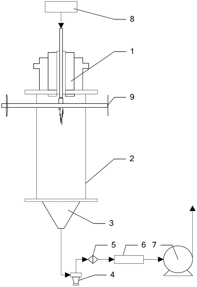
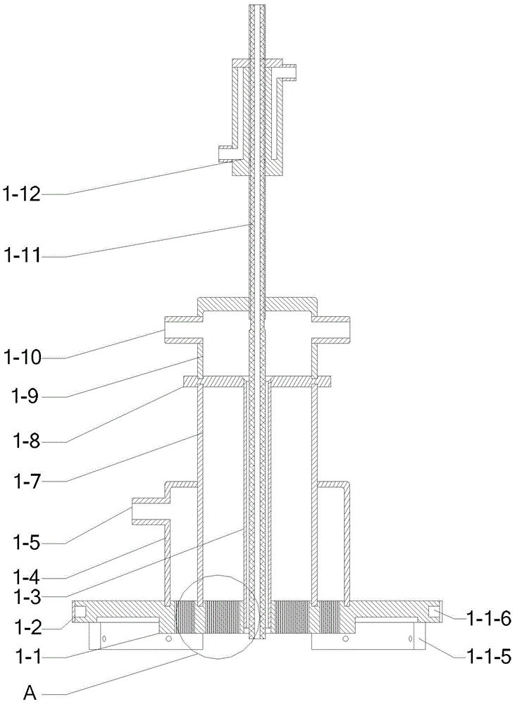
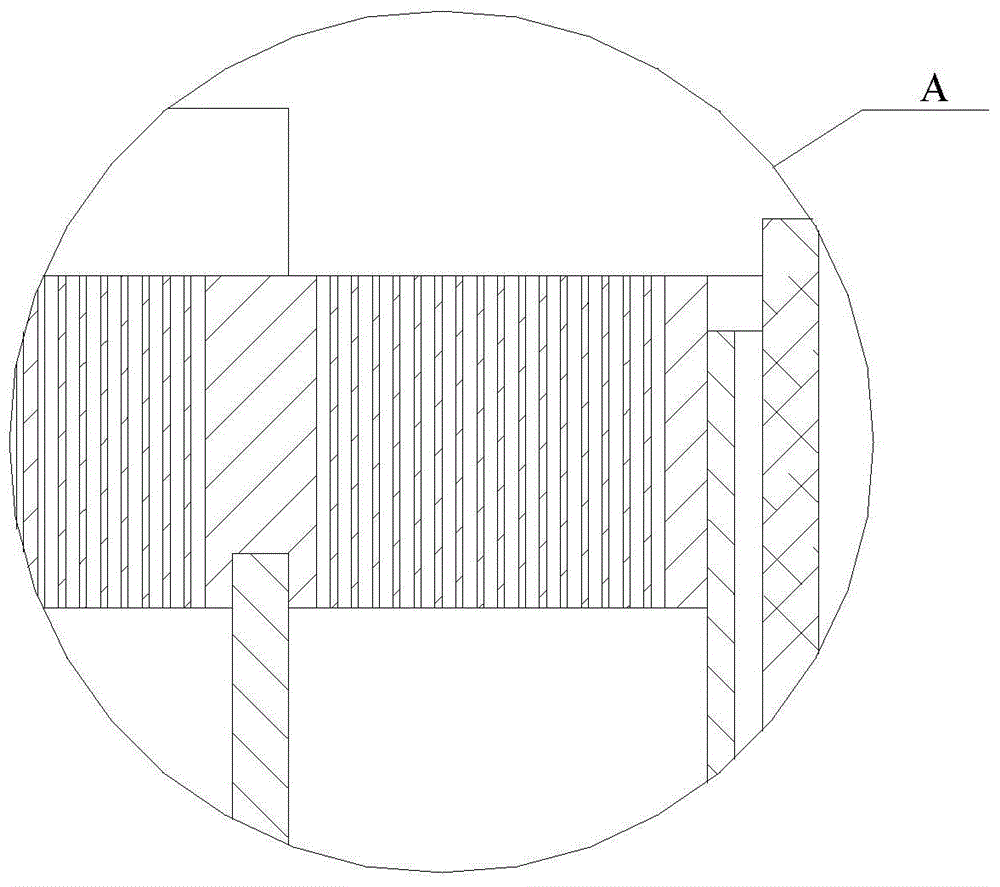
[0032] Specific implementation mode one: refer to Figure 1 to Figure 6 , Figure 9 Specifically illustrate the present embodiment, the pulverized coal flame combustion diagnostic test device described in the present embodiment, it comprises: integrated burner 1, 4 square optical windows 2, tail gas collecting device 3, cyclone separator 4, filter 5, drying Device 6, induced draft fan 7, micro powder feeder 8 and PLIF optical path system 9;

[0033] The space surrounded by 4 square optical windows 2 end to end is used as the combustion chamber of the pulverized coal flame combustion diagnostic test device, and the space is a transparent cube from top to bottom;

[0034]The powder outlet of the micro-powder feeder 8 is connected to the powder inlet end of the integrated burner 1, the flame injection end of the integrated burner 1 is connected to the upper port of the combustion chamber, and the lower port of the combustion chamber is connected to the intake port of the exhaust...

specific Embodiment approach 2

[0054] Specific embodiment two: This embodiment is to further explain the pulverized coal flame combustion diagnostic test device described in specific embodiment one. In this embodiment, the integrated burner 1 also includes: a powder feeding pipe water cooling device 1-12, the The powder feeding pipe water cooling device 1-12 is used for cooling the powder feeding pipe 1-11.

[0055] The powder feeding pipe 1-11 is cooled by the cold air of the secondary air pipe 1-3 and the powder feeding pipe water cooling device 1-12 at the same time, and the temperature balance is maintained during the test.

specific Embodiment approach 3

[0056] Specific implementation mode three: refer to Figure 7 with Figure 8 This embodiment is specifically described. This embodiment is to further illustrate the pulverized coal flame combustion diagnostic test device described in Embodiment 1. In this embodiment, the center of the main body 3-1 of the exhaust gas collection device 3 has a conical through hole , the wide mouth of the conical through hole is the air inlet of the exhaust gas collection device 3, the narrow mouth of the conical through hole is the gas outlet of the exhaust gas collection device 3, and the side wall of the main body 3-1 near the air inlet has a cooling ring. Groove 3-6, the periphery of the cooling groove 3-6 is wrapped with a cooling groove sealing skin 3-2, and the cooling groove sealing skin 3-2 is provided with a through hole 3-3,

[0057] Four arc-shaped connecting pieces (3-7) are arranged around the air inlet of the exhaust gas collection device 3, and each arc-shaped connecting piece (...


PUM

PropertyMeasurementUnit
areaaaaaaaaaaa
areaaaaaaaaaaa
depthaaaaaaaaaa

Abstract

The invention provides a pulverized coal flame burning diagnosis testing device and belongs to the technical field of pulverized coal burning. The pulverized coal flame burning diagnosis testing device aims at solving the problem that an existing experiment device simulating burning of pulverized coal in a hearth of a power station pulverized coal fired boiler cannot simulate an actual pulverized coal burning environment and cannot utilize PLIF system to perform pulverized coal flame burning diagnosis. A very thin flat flame is formed in a flat flame area of a burner boiler plate of the pulverized coal flame burning diagnosis testing device, a 2000K temperature field and a smoke environment similar to the inside of the boiler can be formed. The requirement of a local pulverized coal burning simulating environment can be met. Laser and fluorescence signals can damply pass through trace pulverized coal feeding and light transmitting of a boiler body, a burning chamber formed by 4 square optical windows and provided with a square cross section can reduce the influence on a light path, and high-quality optical measurement can be ensured. A pulverized coal pipe is adjustable in extending length, and it is ensured that the fluorescence signal of pulverized coal flame is detected. The flame shape in the burning chamber and a flow field are approximately and axially symmetric to facilitate experiment measurement and research. The pulverized coal flame burning diagnosis testing device operates under micro negative pressure.

Description

technical field [0001] The invention belongs to the technical field of pulverized coal combustion research. Background technique [0002] my country's primary energy is mainly coal, and pulverized coal combustion is currently the most important combustion method. The concentration of NOx in the exhaust of pulverized coal boilers in my country is relatively high, and NOx is the main precursor and component of photochemical smog and smog. In the face of increasingly serious environmental problems, especially the pollution caused by nitrogen oxide emissions from thermal power plants, the emission limits of nitrogen oxides in the newly formulated national air pollutant emission standards for thermal power plants have reached the most stringent level in the world. Pulverized boiler combustion and denitrification technology uses advanced optical measurement and diagnosis methods to measure and analyze the structure change of pulverized coal flame and the distribution of component...

Claims


Application Information

Patent Timeline
Patent Type & Authority Applications(China)
IPC IPC(8): G01N21/64G01N31/12
Inventor 孙锐邹高鹏张蕾彭江波于欣吴少华
Owner HARBIN INST OF TECH
Learn More