Industrial wastewater photocatalysis reaction treatment system
A photocatalytic reaction and treatment system technology, applied in the field of industrial wastewater photocatalytic reaction treatment system, can solve the problems of high energy consumption, non-recyclable photocatalyst, insufficient contact, etc., achieve low energy consumption, improve land utilization, improve efficiency effect
- Summary
- Abstract
- Description
- Claims
- Application Information
AI Technical Summary
Problems solved by technology
Method used
Image

Examples
Embodiment 1
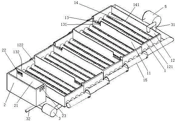
[0041] Embodiment one, see figure 1 , a photocatalytic reaction treatment system for industrial wastewater, including a bubbling tank 1, a blowing pump 5, a magnetic separation device 2 and a sewage pump 3.
[0042] A partition 11 is arranged inside the bubbling tank 1 . There are 4 dividing plates 11. Four partitions 11 divide the bubbling pool 1 into five water tanks 12. The five water tanks are distributed on the same straight line. The water tank 12 extends in the left-right direction. The water tank 12 is provided with an overflow port 13, and the height of the lowest part 131 of the overflow port (ie, the bottom wall of the overflow port) from the bottom surface of the water tank 12 where it is located is 6-13 cm. That is, the depth of water in the water tank 12 has only 6 to 13 centimeters. The overflow ports in adjacent water tanks are staggered along the distribution direction perpendicular to the overflow tanks, that is, the left and right directions in the figur...
Embodiment 2
[0051] Embodiment two, the difference with embodiment one is:
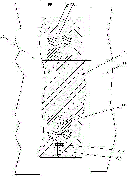
[0052] see image 3 , The blower pump 5 includes a pump casing 52 . The pump housing 52 is connected with an air pump body 53 (ie, an impeller) and a motor 54 for driving the air pump body. The motor 54 and the air pump body 53 are connected together through a rotating shaft 51 . The rotating shaft 51 is supported by the pump housing 52 through two bearings 55 . A refueling chamber 56 is formed between the pump housing 52 and the two bearings 55 . A first gear 58 and a second gear 57 are arranged in the oil filling chamber 56 . The first gear 58 and the second gear 57 mesh together. The first gear 58 is connected with the rotating shaft 51 . The second gear 57 is rotationally connected with the pump casing 52 through a short shaft 571 .
[0053] see Figure 4 , the first gear 58 is provided with a refueling mechanism 8 . The number of refueling mechanisms 8 is equal to the number of teeth of the first gea...
Embodiment 3
[0059] Embodiment three, the difference with embodiment two is:
[0060] see Figure 7 , the rotating shaft 51 is pierced with a circular inner rod 511 . The inner rod 511 is a tubular structure. The inner surface of the rotating shaft 51 is provided with an inner friction layer 512 . The inner rod 511 includes a left rod 5111 and a right rod 5112 . The outer peripheral surfaces of the left rod 5111 and the right rod 5112 are provided with an outer friction layer 5113 . The outer friction layer 5113 covers the inner rod 511 along the circumference of the inner rod 511 . The left end of the left rod 5111 is connected with the rotating shaft 51 through the left energy-absorbing spring 513 . The right end surface of the left rod 5111 is provided with a plurality of first reversing teeth 5114 distributed along the circumferential direction of the left rod. The right end of the right rod 5112 is connected with the rotating shaft 51 through the right energy-absorbing spring 51...
PUM
| Property | Measurement | Unit |
|---|---|---|
| diameter | aaaaa | aaaaa |
Abstract
Description
Claims
Application Information
 - R&D
- Intellectual Property
- Life Sciences
- Materials
- Tech Scout
- Unparalleled Data Quality
- Higher Quality Content
- 60% Fewer Hallucinations
Browse by: Latest US Patents, China's latest patents, Technical Efficacy Thesaurus, Application Domain, Technology Topic, Popular Technical Reports.
© 2025 PatSnap. All rights reserved.Legal|Privacy policy|Modern Slavery Act Transparency Statement|Sitemap|About US| Contact US: help@patsnap.com