Compound molecular pump

A technology of composite molecular pump and pump casing, applied in the direction of pump, pump control, pump device, etc., can solve the problems of molecular pump failure, rotor spindle retention, loss, etc., achieve good corrosion resistance and high temperature resistance, and improve work performance , the effect of reducing the failure rate

Active Publication Date: 2015-09-09
SHANGHAI FUYAO VACUUM TECH CO LTD
View PDF10 Cites 12 Cited by
  • Summary
  • Abstract
  • Description
  • Claims
  • Application Information

AI Technical Summary

Problems solved by technology

However, under the influence of controller failure, external interference or other failures, the magnetic bearing cannot ensure that the rotor main shaft remains at the target position, that is, the main shaft will undergo radial displacement, and the distance between the main shaft and the magnetic bearing will change, so that the rotor will be in contact with the magnetic bearing during high-speed rotation. The stator collided, causing the molecular pump to fail and causing serious losses
[0008] In addition, the pressure, temperature, pH and other conditions of the gas absorbed by the molecular pump will also affect the health performance of the molecular pump and affect the normal use of the molecular pump

Method used


Image

  • Compound molecular pump
  • Compound molecular pump
  • Compound molecular pump

Examples


Embodiment Construction

[0030] Embodiments of the present invention are described below through specific examples, and those skilled in the art can easily understand other advantages and effects of the present invention from the content disclosed in this specification. The present invention can also be implemented or applied through other different specific implementation modes, and various modifications or changes can be made to the details in this specification based on different viewpoints and applications without departing from the spirit of the present invention.

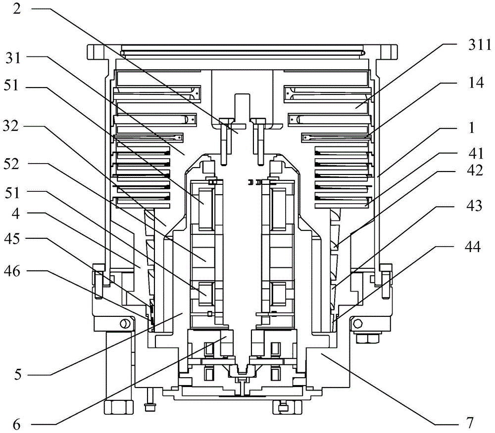
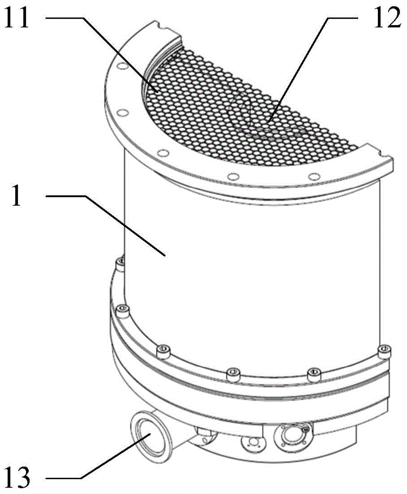
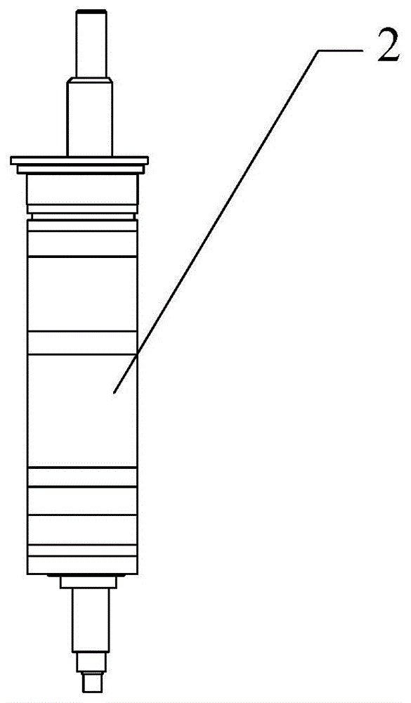
[0031] see Figure 1 to Figure 6 . It should be noted that the diagrams provided in this embodiment are only schematically illustrating the basic idea of ​​the present invention, and only the components related to the present invention are shown in the diagrams rather than the number, shape and shape of the components in actual implementation. Dimensional drawing, the type, quantity and proportion of each component can be changed arb...


PUM


Abstract

The invention provides a compound molecular pump. A plurality of layers of stator blades are sequentially and fixedly mounted on the inner wall of a pump shell in the axial direction, and a main shaft is vertically arranged in the pump shell; rotors comprise a turbine stage rotor and a traction stage rotor; a plurality of layers of rotor blades are sequentially distributed and arranged on the periphery of the turbine stage rotor in the axial direction, and the rotor blades and the stator blades are alternatively arranged in the axial direction and are opposite in the inclined direction; compound spiral groove stators comprise horizontal type spiral groove stators and vertical type spiral groove stators, wherein the horizontal type spiral groove stators and the vertical type spiral groove stators are connected into a whole; and the rotor blades on the bottommost layer match the horizontal type spiral groove stators. Sensors and heating devices are arranged in material sedimentary areas in molded line spiral flow guide grooves, and the lower end of the main shaft is sleeved with a radial magnetic bearing. The compound molecular pump is compact in structure, and under the premise of the large pumping speed and the high compression ratio, rotating speed sudden increasing, high temperature resisting and corrosion resisting of the rotors in the short time can be achieved; material sedimentation can be effectively reduced; and the health state of the molecular pump can be monitored in real time, and the molecular pump can be prevented from losing efficacy in time.

Description

technical field [0001] The invention relates to a molecular pump, in particular to a composite molecular pump. Background technique [0002] After nearly 100 years of development, the molecular pump has been widely used in engineering practice, mainly because it has a high compression ratio for gases with large molecular weight, and can obtain a clean vacuum environment. In the system, the oil diffusion pump has been replaced by a turbomolecular pump. As a very important subsystem of semiconductor, glass coating and liquid crystal display equipment, turbomolecular pump is widely used in etching, low pressure chemical vapor deposition (Low Pressure Chemical Vapor Deposition, referred to as LPCVD), metal organic chemical vapor deposition (Metal -organic Chemical Vapor Deposition, referred to as MOCVD), ion implantation and sputtering processes. The main problem of turbomolecular pumps is that when the inlet pressure is on the order of 1.33Pa, its effective pumping speed will...

Claims


Application Information

Patent Timeline
Patent Type & Authority Applications(China)
IPC IPC(8): F04D25/06F04D19/04F04D29/32F04D29/38F04D29/02F04D29/54F04D29/58F04D27/00
Inventor 李文煜
Owner SHANGHAI FUYAO VACUUM TECH CO LTD
Why Eureka
Try Eureka