
Sewage heat exchange device capable of self-cleaning and scale inhibition

A heat exchange device and self-cleaning technology, which is applied in the direction of cleaning heat transfer devices, heat exchanger types, indirect heat exchangers, etc., can solve problems such as inability to achieve scaling self-cleaning, easy scaling, flow channel blockage, etc.

Inactive Publication Date: 2017-03-08
BEIJING UNIV OF CIVIL ENG & ARCHITECTURE
View PDF2 Cites 0 Cited by
  • Summary
  • Abstract
  • Description
  • Claims
  • Application Information

AI Technical Summary

Problems solved by technology

The heat exchange efficiency of the immersion heat exchange device is low, the floor area is large, and it is easy to scale and difficult to clean; the shell and tube heat exchange device has high heat exchange efficiency before the heat exchange surface is scaled, but the sewage is in the tube side or The flow in the shell side can easily cause dirt to form and accumulate in the flow channel. In severe cases, it will cause blockage in the flow channel. The heat exchange efficiency of the heat exchange surface after scaling will drop sharply. The structure also makes it more difficult to clean the dirt. The shell-and-tube heat exchange device usually needs to be used together with the anti-blocking machine, but the anti-blocking machine usually has a certain removal effect on large-scale dirt below 2mm, and it still cannot prevent and Improve the generation of dirt such as soft dirt on the heat exchange surface, and add an anti-blocking machine to greatly increase the cost of the heat exchange device
The existing schemes for improving the sewage shell-and-tube heat exchange device also increase the channel for sewage circulation to form a "wide flow channel". Although the probability of sewage clogging in the flow channel can be reduced, scaling on the heat exchange surface still exists. And greatly increase the size and floor area of ​​the heat exchange device, the heat exchange efficiency will also decrease; the applicant has disclosed a sewage heat recovery device with anti-scaling in Chinese patents CN202747844U and CN202747842U, which adopts spray heat exchange The method requires the use of a heat exchange surface of a specific size and processing method, such as opening grooves of a specific size on the heat exchange surface, adding ribs, etc., the processing difficulty and cost of the heat exchanger are significantly increased, and the overall size of the heat exchanger is also large , and the realization method of scale inhibition is to reduce the induction period of scale formation, and there is still the phenomenon of continuous growth of scale in long-term continuous operation, which limits the scale inhibition effect and reliability of the long-term operation of the device, and the device is easy to accumulate after long-term operation. Scale and cannot achieve self-cleaning of scaling

Method used


Image

  • Sewage heat exchange device capable of self-cleaning and scale inhibition
  • Sewage heat exchange device capable of self-cleaning and scale inhibition
  • Sewage heat exchange device capable of self-cleaning and scale inhibition

Examples


Embodiment 1

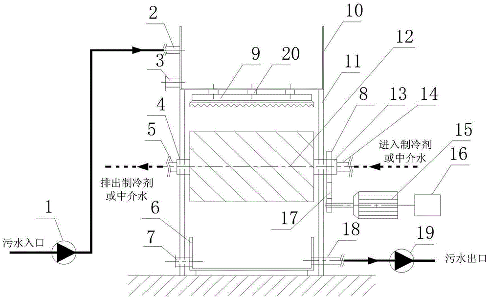
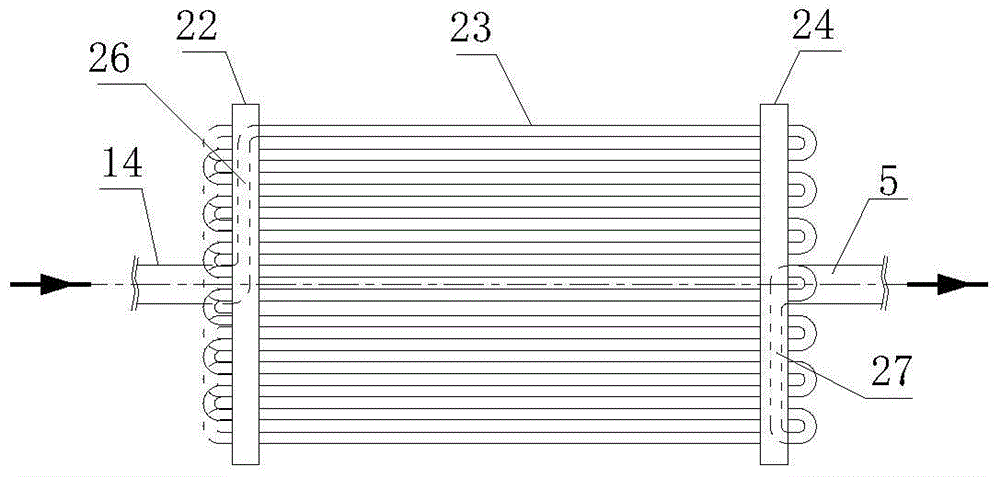
[0055] The structure of the sewage heat exchange device in this embodiment adopts the structure of the sewage heat exchange device given above, wherein the heat exchange coil tube row 23 is a circular straight tube made of copper. The heat exchange device is mainly suitable for heat exchange of sewage with less large-scale dirt and high water quality, such as sewage after primary treatment and sewage after secondary treatment in sewage treatment plants.

[0056] The operation process of the sewage heat exchange device is as follows:

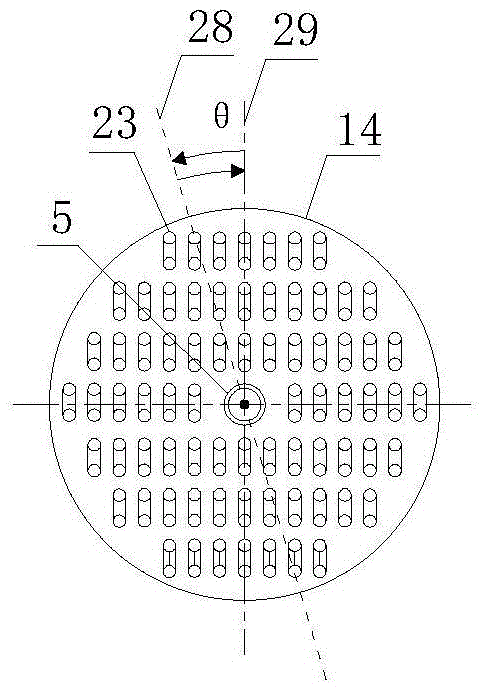
[0057] (1) If figure 1 , Figure 2-a , Figure 2-b , Figure 2-cAs shown, the sewage is transported through the sewage lifting pump 1 to the sewage inlet 2 of the upper water supply tank through the pipeline, and the sewage enters the upper water supply tank 10, and the sewage passes through the water distributor 20 at the bottom of the upper water supply tank and flows into the water distributor 9 of the sawtooth overflow tank. Under the act...

Embodiment 2

[0062] For sewage with more large-scale dirt and low water quality, such as raw sewage. The difference between this embodiment and Embodiment 1 is that during the operation process of the sewage heat exchange device, it runs continuously for 3 days or more, and takes the line connecting the frame centers of the wheel-type coil frames 22 and 24 as the axis to control the water flow through rotation. The device 16 controls the motor 15 to drive the wheel type heat exchange tube column 12 to rotate clockwise or counterclockwise, as Figure 2-b As shown, the vertical axis of symmetry of the wheel-type heat exchange tube row 12 turns from a vertical angle 29 to a θ angle 28. The θ angle is the rotation angle, and the rotation angle can vary from 170 to 190 degrees. Other steps are the same as in Embodiment 1.

Embodiment 3

[0064] For sewage containing more elongated pollutants, such as sewage containing hair. The difference between this embodiment and one of the first or second embodiments is that: during the operation of the self-cleaning and scale-inhibiting sewage heat exchange device, it operates continuously for 1 day or more, such as figure 1 As shown, taking the line connecting the frame centers of the wheel-type coil frames 22 and 24 as the axis, the motor 15 is controlled by the rotation controller 16 to drive the wheel-type heat exchange tube row 12 to rotate clockwise or counterclockwise, as shown in FIG. Figure 2-b As shown, the vertical axis of symmetry of the wheel-type heat exchange tube row 12 turns from a vertical angle 29 to a θ angle 28, where the θ angle is the rotation angle, and the rotation angle can vary from 80 to 100 degrees. Others are identical to embodiment one or two.


PUM


Abstract

The invention discloses a sewage heat exchange device, and belongs to the field of heat exchange equipment. The sewage heat exchange device comprises an upper water supply tank provided with a sewage inlet and a water distributor connecting pipe at the bottom, a sawtooth overflow tank water distributor arranged on the lower surface of the water distributor connecting pipe of the upper water supply tank, a heat exchange pipe line arranged below the sawtooth overflow tank water distributor and provided with a heat exchange medium inlet and a heat exchange medium outlet, and a water receiving tank arranged below the heat exchange pipe line and provided with a sewage outlet. As sewage vertically and uniformly drips on the surface of the heat exchange pipe line, for flowing a heat exchange medium inside, through the sawtooth overflow tank water distributor under the effect of gravity in a droplet or liquid column form, a liquid film continuously flowing on the surface of the heat exchange pipe line is formed to exchange heat with the heat exchange medium in the heat exchange pipe line; as the sewage flows on the surface of the heat exchange pipe line by the continuous flowing liquid film, the generation of such dirt as soft dirt on the heat exchange surface can be largely relieved and improved; and no sewage flows in a channel, so that no blockage phenomenon is generated, the dirt inhibiting effect in long-time continuous operation can be kept, and the heat exchange efficiency is improved.

Description

technical field [0001] The invention relates to the field of heat exchange equipment, in particular to a sewage heat exchange device capable of self-cleaning and scale inhibition. Background technique [0002] The heat in the sewage discharged by the city accounts for about 15% of the total heat discharged in the city. The urban sewage has a large amount and the water temperature is higher than ordinary water sources such as groundwater and surface water. It is a good renewable energy source. The sewage source heat pump system is used to extract its heat for recovery. The use of low-level energy for urban cooling and heating has good energy-saving and environmental protection significance. At present, the outstanding problem in extracting heat energy from sewage by the sewage source heat pump system lies in the heat energy extraction link. The sewage contains a large number of floating and suspended solid particles, colloidal and gel-like diffusers and other pollutants, whic...

Claims


Application Information

Patent Timeline
Patent Type & Authority Patents(China)
IPC IPC(8): F28D11/04F28F5/00F28F21/08F28F27/00F28G9/00
CPCY02P80/10
Inventor 那威宋艳
Owner BEIJING UNIV OF CIVIL ENG & ARCHITECTURE
Learn More