
Two-dimensional reflection type supersonic wave wind speed anemoscope and measuring method

An anemometer, wind speed and direction technology, applied in the direction of fluid velocity measurement, velocity/acceleration/impact measurement, measuring device, etc., can solve the problems of many measurements, shortened service life, fast wear of moving parts, etc.

Active Publication Date: 2015-09-09
UNIV OF SCI & TECH OF CHINA
View PDF4 Cites 25 Cited by
  • Summary
  • Abstract
  • Description
  • Claims
  • Application Information

AI Technical Summary

Problems solved by technology

However, this kind of anemometer has relatively high requirements for the measurement environment, and because the sealing problem of the instrument is not solved, it cannot work normally in the sandstorm weather in the north, and the moving parts will be stuck due to freezing in the low temperature environment; at the same time, the mechanical Due to the existence of many moving parts, the mechanical anemometer wears quickly and shortens the service life; in addition, due to the limitation of the mechanical structure and measurement principle, the sensitivity of the mechanical anemometer is low
Most of the existing ultrasonic anemometers based on the time difference method adopt the time-sharing principle, that is, a pair of ultrasonic sensors send and receive signals in turn, requiring many measurements, and the circuit structure is complex, often resulting in large differences in measurement results due to multiple measurements. error

Method used


Image

  • Two-dimensional reflection type supersonic wave wind speed anemoscope and measuring method
  • Two-dimensional reflection type supersonic wave wind speed anemoscope and measuring method
  • Two-dimensional reflection type supersonic wave wind speed anemoscope and measuring method

Examples


Embodiment Construction

[0042] The present invention will be further described below in conjunction with the accompanying drawings and specific embodiments.

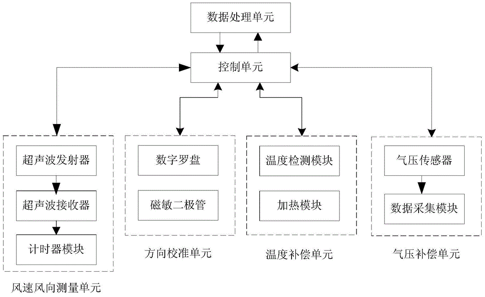
[0043] Such as figure 1 As shown, the core of the ultrasonic anemometer of the present invention is the control unit, which is connected with the data processing unit to process relevant data during the measurement process and obtain the final wind speed and direction data. It is connected with the wind speed and direction measurement unit to control the transmission and reception of ultrasonic waves, and start and close the timer module through interrupts to obtain the propagation time of ultrasonic waves. It is connected with the direction calibration unit to determine the reference direction, that is, the direction of the geographic north pole (magnetic south pole), which is used to calibrate the wind direction data to make it consistent with the actual wind direction. It is connected with the temperature compensation module, and judges whe...


PUM


Abstract

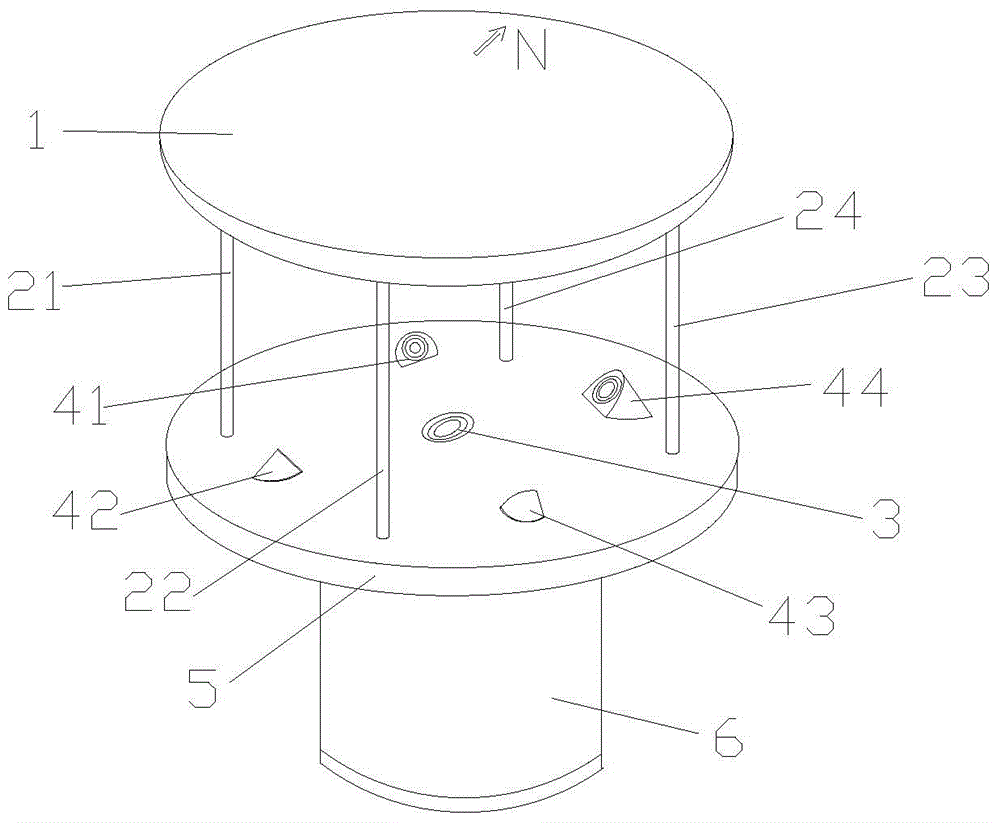
The invention discloses a two-dimensional reflection type supersonic wave wind speed anemoscope and a measuring method. The wind speed anemoscope comprises a control unit, a data processing unit, a wind speed and wind direction measuring unit, a direction calibration unit, a temperature compensation unit and an air pressure compensation unit. The wind speed and wind direction measuring unit is composed of a supersonic wave emitter, a supersonic wave receiver and a timer module; the direction calibration unit is composed of a digital compass and a magnetosensitive diode; the temperature compensation unit is composed of a temperature detection module and a heating module; and the air pressure compensation unit is composed of an air pressure sensor and a data acquisition module. According to the invention, one integrated ultrasonic sensor is employed for emission, one of echo signals is received, four receiving sensors receive and reflect the echo signals, the five sensors are arranged on the same horizontal plane, a wind speed and a wind direction can be calculated simply by use of a time difference between emission and receiving once, the measuring principle is simple, the measuring precision is improved, the service life of the instrument is prolonged, and the anemoscope and the method are suitable for various severe measuring environments.

Description

technical field [0001] The invention belongs to the technical field of wind speed and direction measurement, and in particular relates to a two-dimensional reflective ultrasonic wind speed and direction instrument and a measurement method. Background technique [0002] Anemometers play an important role in the fields of meteorology, civil aviation, highways, agriculture and new energy. At present, the mechanical anemometer is mostly used, which mainly obtains basic measurement information through the rotation of the impeller driven by the wind force, converts the angular velocity of the impeller rotation or the number of revolutions of the impeller into electrical signals, and calculates the wind speed based on this. However, this kind of anemometer has relatively high requirements for the measurement environment, and because the sealing problem of the instrument is not solved, it cannot work normally in the sandstorm weather in the north, and the moving parts will be stuck ...

Claims


Application Information

Patent Timeline
IPC IPC(8): G01P5/24G01P13/02
CPCG01P5/24
Inventor 康宇崔凌云陈守胜胡峰李泽瑞
Owner UNIV OF SCI & TECH OF CHINA
Learn More