
Flue gas waste heat recovery system and recovery method and application thereof

A flue gas waste heat recovery system technology, applied in the field of flue gas waste heat recovery, can solve problems such as cost increase, achieve the effect of improving efficiency, improving heat utilization value and economic benefits, and optimizing heat utilization methods

Active Publication Date: 2015-09-23
SHANGHAI YOUHUA PROCESS INTEGRATED TECH CO LTD +1
View PDF9 Cites 3 Cited by
  • Summary
  • Abstract
  • Description
  • Claims
  • Application Information

AI Technical Summary

Problems solved by technology

[0008] Although the above systems provide the thermal efficiency of the heating furnace, they all need to add additional equipment, which increases the cost

Method used


Image

  • Flue gas waste heat recovery system and recovery method and application thereof
  • Flue gas waste heat recovery system and recovery method and application thereof

Examples


Embodiment 1

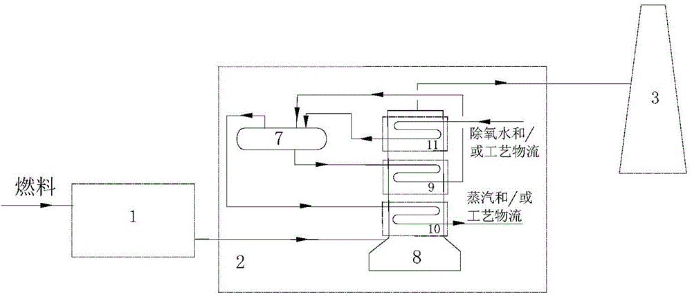
[0036] This embodiment adopts figure 1 The system shown performs flue gas waste heat recovery. Fuel and air heated by the air preheater 4 from the blower 6 enter the heating furnace radiant chamber 1, and the flue gas leaving the heating furnace radiant chamber 1 is the flue gas in the convection chamber 2 of the heating furnace The inlet enters the furnace body 8, and the material is directly added to the material inlet of the steam drum 7. A part of the liquid in the steam drum 7 enters the evaporation section 9 from the downcomer of the steam drum 7 to be heated to produce steam, and part of the liquid material becomes steam to form a gas-liquid mixture , The gas-liquid mixture leaves the evaporation section 9 and enters the steam drum 7, where the gas-liquid separation is carried out in the steam drum 7, and the liquid falls into the liquid space in the steam drum 7; the other part of the liquid in the steam drum 7 is connected to the material inlet of the steam drum 7 After...

Embodiment 2

[0039] Except that the coal-saving section 11 in the convection chamber 2 of the heating furnace is drawn out while one furnace tube in the evaporation section 9 in the convection chamber 2 of the heating furnace is drawn out, the other processes are the same as in Embodiment 1.

[0040] It increases the temperature of the flue gas at the outlet of the convection chamber 2 of the heating furnace to 250-350°C, thereby effectively increasing the temperature of the air entering the radiation chamber of the heating furnace, and finally achieves the purpose of rationally optimizing the heat energy distribution of the flue gas and reducing the fuel consumption of the heating furnace.

Embodiment 3

[0042] Except that the coal-saving section 11 in the convection chamber 2 of the heating furnace is drawn out while three furnace tubes in the evaporation section 9 in the convection chamber 2 of the heating furnace are drawn out, the other processes are the same as in Embodiment 1.

[0043] It increases the temperature of the flue gas at the outlet of the convection chamber 2 of the heating furnace to 250-350°C, thereby effectively increasing the temperature of the air entering the radiation chamber of the heating furnace, and finally achieves the purpose of rationally optimizing the heat energy distribution of the flue gas and reducing the fuel consumption of the heating furnace.


PUM


Abstract

The invention provides a flue gas waste heat recovery system and a recovery method and application thereof. The flue gas waste heat recovery system comprises a heating furnace radiation chamber, a heating furnace convection chamber, an air pre-heater, an induced draft fan, an air blower and a chimney. The heating furnace radiation chamber, the heating furnace convection chamber, the air pre-heater, the induced draft fan and the chimney are connected in sequence, and an outlet of the air blower is connected with the air inlet of the air pre-heater and the air inlet of the heating furnace radiation chamber. A material is fed into a steam pocket, a steam pocket downtake pipe is connected with an evaporation section inlet and a steam pocket inlet, an evaporation section outlet is connected with a steam pocket steam inlet, and a steam pocket steam outlet is connected with a superheat section inlet. The air pre-heater is added between the heating furnace convection chamber and the chimney of the flue gas waste heat recovery system, a flue gas heat utilization mode is reasonably optimized between a heating furnace and a waste heat boiler according to the situations of public works in the whole system under the situation that change of an original convection chamber is very small, and heat utilization value and economic benefit are improved.

Description

Technical field [0001] The field of flue gas waste heat recovery of the present invention particularly relates to a flue gas waste heat recovery system for reforming a heating furnace and its recovery method and application, and in particular to a flue gas waste heat based on reforming a heating furnace that generates steam in a convection chamber Recovery system and its recovery method and use. Background technique [0002] The flue gas waste heat resource is a secondary energy source, which is the product of primary energy or combustible material conversion, or the heat emitted during the fuel combustion process after completing a certain process. [0003] In the process of applying the heating furnace to provide heat for the process, the liquid (gas) fuel is burned in the heating furnace radiant chamber (furnace) to generate high-temperature flue gas and use it as a heat carrier to flow to the convection chamber and then exhaust from the chimney. Among them, the waste heat boil...

Claims


Application Information

Patent Timeline
Patent Type & Authority Applications(China)
IPC IPC(8): F22B1/18F22D1/36
Inventor 王剑峰孙虎良沈雪松
Owner SHANGHAI YOUHUA PROCESS INTEGRATED TECH CO LTD
Learn More