Magneto-rheological damper with mixed flow type fluid flowing channel

A magneto-rheological damper and liquid flow channel technology, applied in the direction of gas-liquid shock absorber, shock absorber, shock absorber, etc., can solve the difficulty of effective damping gap length, magnetorheological damper failure, increase effective damping Clearance and other problems, to achieve the effect of increasing the effective damping length and shear area, increasing the yield stress, and widening the dynamic adjustment range

Active Publication Date: 2015-10-07
EAST CHINA JIAOTONG UNIVERSITY
View PDF7 Cites 9 Cited by
  • Summary
  • Abstract
  • Description
  • Claims
  • Application Information

AI Technical Summary

Problems solved by technology

A common method is to reduce the width of the damping gap of the magnetorheological damper. However, when the magnetorheological fluid is left unused for a long time and is used again, particles are prone to precipitate and block the damping gap, resulting in the failure of the magnetorheological damper.
The second is to increase the length of the effective damping gap, but this will significantly increase the volume of the magnetorheological damper, occupy more installation and use space, and increase the manufacturing cost accordingly
[0006] Based on this, in the actual design process, it is difficult to simultaneously increase the magnetic induction intensity in the effective damping gap and increase the length of the effective damping gap

Method used


Image

  • Magneto-rheological damper with mixed flow type fluid flowing channel
  • Magneto-rheological damper with mixed flow type fluid flowing channel
  • Magneto-rheological damper with mixed flow type fluid flowing channel

Examples


Embodiment Construction

[0024] Below in conjunction with accompanying drawing and embodiment the present invention will be further described:

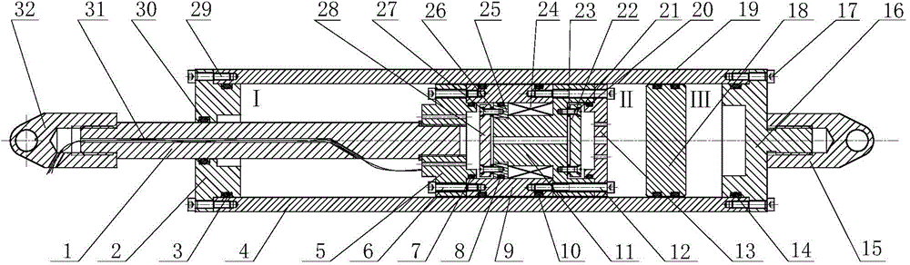
[0025] Such as figure 1 As shown, the present invention includes: piston rod 1, damper left end cover 2, sealing ring I3, sleeve 4, piston left end cover 5, screw I6, sealing ring II7, sealing ring III8, valve sleeve 9, sealing ring IV10, valve Core 11, screw Ⅱ12, piston right end cover 13, sealing ring Ⅴ14, right lug 15, damper right end cover 16, screw Ⅲ17, floating piston 18, sealing ring Ⅵ19, sealing ring Ⅶ20, slotted countersunk screw Ⅰ21, right guide Magnetic disk 22, spacer Ⅰ23, excitation coil 24, positioning disk 25, spacer Ⅱ26, slotted countersunk screw Ⅱ27, left magnetic disk 28, screw Ⅳ29, sealing ring Ⅷ30, lead hole 31 and left lifting ear 32.

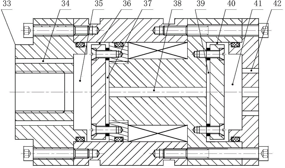
[0026] figure 2 It is a structural schematic diagram of the mixed flow type liquid flow channel in the combined piston of the present invention. Among them, 33 is a combined piston; 4 through holes A...


PUM


Abstract

The invention discloses a magneto-rheological damper with a mixed flow type fluid flowing channel. The magneto-rheological damper is mainly composed of a piston rod, a damper end cover, a sleeve, a piston end cover, a valve bush, a valve element, a floating piston, a magnet exciting coil, a positioning disc, magnetic conductive discs, a lifting lug and the like. A fluid flowing channel among the left magnetic conductive disc, the valve bush and the valve element forms a first section of effective damping gap and a second section of effective damping gap. A fluid flowing channel between the right magnetic conductive disc and the valve element forms a third section of effective damping gap and a fourth section of effective damping gap. When electric conduction is carried out on the magnet exciting coil, the four sections of effective damping gaps generate a magnetic field with a certain size, the viscosity of magneto-rheological fluid flowing through the four sections of effective damping gaps is increased, the yield stress is improved, and therefore pressure difference is formed between a first cavity and a second cavity of the damper. The damping force can be effectively controlled by controlling the magnitude of applied current. The magneto-rheological damper is wide in damping force dynamic adjustment range, simple in structure, small in size and particularly applicable to vibration damping systems of railways, automobiles, bridges and the other structures.

Description

technical field [0001] The invention relates to a magneto-rheological damper, in particular to a magneto-rheological damper with a mixed-flow liquid flow channel. Background technique [0002] The magnetorheological damper is a new type of intelligent damping device widely used in semi-active control systems. It mainly applies a certain amount of current to the excitation coil in the winding groove of the damper piston to generate a magnetic field to change the yield strength of the magnetorheological fluid flowing through the liquid flow channel, thereby dynamically changing the output damping force. [0003] The characteristics of millisecond-level response speed, large control range and large damping force output of the magneto-rheological damper make it an excellent semi-active actuator in the field of industrial applications. At present, magnetorheological dampers have been widely used in vibration reduction and anti-seismic systems of buildings and bridges, and vibrat...

Claims


Application Information

Patent Timeline
Patent Type & Authority Applications(China)
IPC IPC(8): F16F9/53F16F9/34F16F9/06
CPCF16F9/06F16F9/34F16F9/53
Inventor 胡国良刘丰硕廖明科李卫华
Owner EAST CHINA JIAOTONG UNIVERSITY
Why Eureka
Try Eureka