Robot cartesian space trajectory planning method

A Cartesian space and robotics technology, applied in the direction of instruments, adaptive control, attitude control, etc., can solve problems that affect the successful execution of tasks, cannot be solved, and the singularity of the planning path

Active Publication Date: 2015-10-07
张耀伦
View PDF6 Cites 62 Cited by
  • Summary
  • Abstract
  • Description
  • Claims
  • Application Information

AI Technical Summary

Problems solved by technology
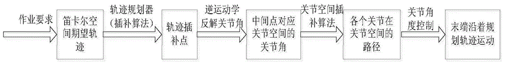
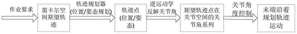
The current Cartesian coordinate space planning method has a large computational workload, and the attitude planning problem is complex, which leads to the possibility that the planned trajectory may approach or pass through the singular point, resulting in unsolvable consequences
Especially for robotic arms with few degrees of freedom, when the attitude planning is unsuccessful, the goal of avoiding singular positions is often achieved by sacrificing the accuracy of the end pose. However, when performing target capture, fine manipulation, etc., the sacrifice of the end pose accuracy affects the performance of tasks. successfully executed
[0009] Therefore, planning in joint space is acceptable for grasping operations with low path requirements, but when there are strict trajectory requirements, such as welding, complex algorithms are needed to ensure accuracy, and trajectory planning in Cartesian space The accuracy is unmatched by this method based on joint space planning
However, in terms of attitude planning, due to its nonlinearity and coupling, most existing algorithms use interpolation schemes, which have poor flexibility. The singularity of the planned path, even the unsolvable situation

Method used


Image

  • Robot cartesian space trajectory planning method
  • Robot cartesian space trajectory planning method
  • Robot cartesian space trajectory planning method

Examples


Embodiment 1

[0115] Example 1: Series five-joint Katana and youBot robotic arms

[0116] Manipulator features: the main control joint c of the two is joint 1, and the self-optimizing joint so is joint 5. If there is no adjustment joint ft, then th=4, mh=3, bh=2, c=1, see Figure 8 with Picture 9 .

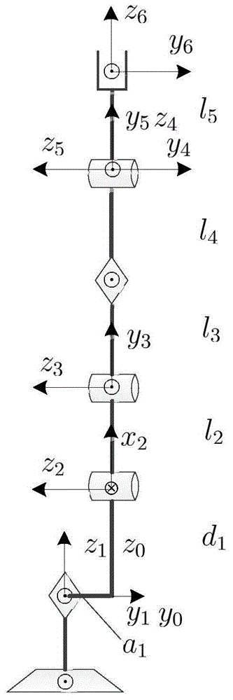
[0117] Step 1: Establish the linkage coordinate system: establish the Z-axis and X-axis of the robot linkage according to the DH method. The base coordinate system is fixed to the base, and each joint coordinate system is established in turn, and the rotation angle of each joint axis is named Respectively θ 1 , Θ 2 , Θ 3 , Θ 4 , Θ 5 ; Suppose the vertical state is the initial position.

[0118] Step 2: Take KUKAyouBot as an example, when a 1 =0 is the Katana arm, the solution process of positive kinematics

[0119] Table 1. D-H connecting rod parameter table of robotic arm

[0120]

[0121]

[0122] T 0 B = 1 0 0 a 0 0 1 0 0 0 0 1 ...

Embodiment 2

[0220] Example 2: Series five-joint Pioneer-arm arm and series six-joint PUMA560 arm

[0221] Manipulator features: the main control joint c of the two is joint 1, the adjustment joint ft is 4, the latter has a self-optimizing joint so is joint 6, and the former does not exist, then th=4, mh=3, bh=2, c= 1. See Picture 10 with Picture 11 . Among them, the series six-joint type PUMA560 can be regarded as the series five-joint type Pioneer type, which is the expansion of the under-degree-of-freedom manipulator to achieve five solutions to six.

[0222] Step 1: Establish the linkage coordinate system: Establish the Z-axis and X-axis of the robot linkage according to the DH method. The base coordinate system is fixed to the base, and each joint coordinate system is established in turn, and the rotation angle of each joint axis is named Respectively θ 1 , Θ 2 , Θ 3 , Θ 4 , Θ 5 ; Suppose the vertical state is the initial position.

[0223] Step 2: Take Pioneer-arm as an example, the pos...

Embodiment 3

[0343] Embodiment 3: Series-connected six-joint humanoid robot humanoid legs and extended redundant legs

[0344] As there is a situation where it can move or rotate in or around the base coordinate system x, y, z directions, the projection position is affected by the movement along the axial direction. At this time, it is necessary to combine the end attitude to achieve an accurate solution θ c the goal of. The five-axis linkage CNC machine tool can be regarded as a tandem manipulator, with three joints moving along the base coordinate system x, y, and z directions.

[0345] Features: For the humanoid leg of a humanoid robot, the main control joint c is joint 1, and the self-optimizing joint so is the redundant leg end joint. There is no adjustment joint ft. The joint positions of joints 2 and 3 and joints 5 and 6 are coincident respectively. Then th=6, mh=4, bh=2, c=1, see Picture 12 with Figure 13 .

[0346] Step 1: Establish the linkage coordinate system: Establish the Z-axis...


PUM


Abstract

The invention discloses a robot cartesian space trajectory planning method. The method includes establishing a connecting rod coordinate system and obtaining a forward kinematic equation through a kinetic modeling analysis method; solving the rotating angles of a master control joint and a middle joint according to the vector geometric property and trajectory planning requirement of the robot; seeking a relation equation including introduced variables and solving the rotating angle of the corresponding joint by means of the kinetic modeling analysis method and the solved joint rotating angle; determining whether the pose position can be reached through a vector geometric method when the trajectory planning is carried out in a task space with obstacles; and planning the continuous time variant attitudes of coupled position information to complete the planning tasks. According to the method, extraneous roots can be prevented, efficient solutions can be screened and matched, strange paths can be effectively avoided, and meanwhile, the defects of complex end trajectory planned by the joint space can be prevented and optimized.

Description

Technical field [0001] The invention relates to a method for planning a cartesian space trajectory of a robot, and relates to inverse kinematics and attitude planning. Background technique [0002] The depth and breadth of the application of industrial robots has become an important indicator of a country's manufacturing level and technological level. Since the first industrial robot was applied to General Motor’s production line in 1962, robotics technology has developed rapidly. Especially, the robot revolution is expected to become the “third time” under the background of increasing labor costs and the concept of “Industry 4.0”. The “Industrial Revolution” is an important entry point and growth point. At present, China has become the world’s largest robot market. In May 2015, the State Council issued "Made in China 2025", which clearly stated that it should focus on supporting the development and application of robotics technology and listed it as One of the ten key areas. [...

Claims


Application Information

Patent Timeline
Patent Type & Authority Applications(China)
IPC IPC(8): G05D1/08G05D1/10G05B13/04
Inventor 张耀伦
Owner 张耀伦
Why Eureka
Try Eureka