
LED pulse detection system based on surge current restriction

A surge current and pulse detection technology, which is applied in electric light sources, lamp circuit layout, lighting devices, etc., can solve problems such as high temperature, excessive circuit current, unstable driving performance, etc., achieve high sensitivity, prolong service life, The effect of protecting the LED lamp group

Inactive Publication Date: 2015-10-07
CHENGDU JIESHENG TECH CO LTD
View PDF0 Cites 0 Cited by
  • Summary
  • Abstract
  • Description
  • Claims
  • Application Information

AI Technical Summary

Problems solved by technology

[0004] The purpose of the present invention is to overcome the defects of the current LED drive system that the circuit current is too large and the temperature is high, so that its drive performance is unstable, and to provide a stable LED pulse detection system based on linear drive

Method used


Image

  • LED pulse detection system based on surge current restriction
  • LED pulse detection system based on surge current restriction
  • LED pulse detection system based on surge current restriction

Examples


Embodiment

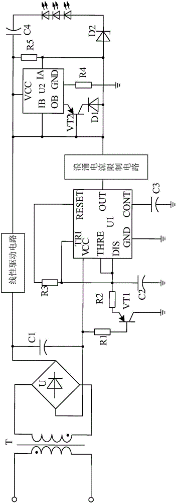
[0022] Such as figure 1 As shown, the present invention mainly consists of a transformer T, a rectification filter circuit connected to the secondary side of the transformer T, a pulse error detection circuit connected to the rectification filter circuit, and a processing circuit connected to the pulse error detection circuit and the rectification filter circuit at the same time, It consists of a voltage stabilizing circuit connected with the processing circuit, a surge current limiting circuit arranged between the pulse error detection circuit and the processing circuit, and a linear drive circuit connected in series between the rectification and filtering circuit and the processing circuit.

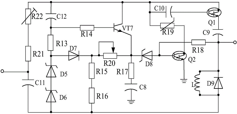
[0023] The inrush current limiting circuit as image 3 As shown, it consists of PDP type Linton tube Q1, PDP type Linton tube Q2, triode VT7, inductor L, resistor R13, resistor R14, resistor R15, resistor R16, resistor R17, resistor R18, thermistor R19, resistor R20, Resistor R21, resi...


PUM


Abstract

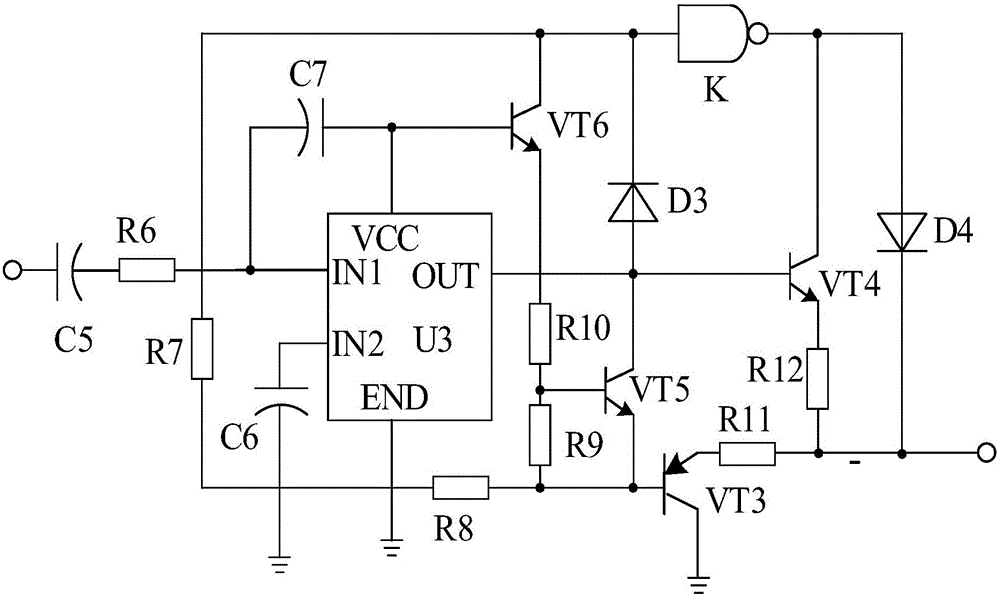
The invention discloses a linear driving-based LED (light-emitting diode) pulse detecting system. The system mainly comprises a transformer T, a rectifier-filter circuit, a pulse error detecting circuit, a processing circuit and a voltage-stabilizing circuit, wherein the rectifier-filter circuit is connected with the secondary side of the transformer T; the pulse error detecting circuit is connected with the rectifier-filter circuit; the processing circuit is simultaneously connected with the pulse error detecting circuit and the rectifier-filter circuit; the voltage-stabilizing circuit is connected with the processing circuit. The system is characterized in that a linear driving circuit is also connected between the rectifier-filter circuit and the processing circuit and comprises a driving chip U3, a triode VT3, a triode VT4, a triode VT5, a triode VT6, a polar capacitor C5 and the like, wherein the anode of the polar capacitor C5 is connected with the rectifier-filter circuit and the cathode of the polar capacitor C5 is connected with the IN1 pin of the driving chip U3 through a resistor R6. According to the system, the driving performance of an LED driving system can be improved by the linear driving circuit, so that the effect of protecting an LED lamp is achieved.

Description

technical field [0001] The invention relates to an electronic system, in particular to an LED pulse detection system based on surge current limitation. Background technique [0002] As a new type of energy-saving light source, LED lights have been widely accepted and adopted by people due to their environmental protection, energy saving, long life, and small size. Since LED is a semiconductor device with sensitive characteristics and has negative temperature characteristics, the LED drive system plays a very important role in promoting the LED to be in a stable and reliable working state during the application process. [0003] However, the circuit current of the current LED driving system is too large and the temperature is high, so that its driving performance is unstable, which greatly affects the normal operation of the LED lamp and is easily damaged. Contents of the invention [0004] The purpose of the present invention is to overcome the defects of the current LED ...

Claims


Application Information

Patent Timeline
Patent Type & Authority Applications(China)
IPC IPC(8): H05B37/02
Inventor 雷明方
Owner CHENGDU JIESHENG TECH CO LTD
Learn More