Heat collecting plate core and flat-plate type solar thermal collector

A technology of solar heat collectors and heat-absorbing plate cores, applied in the field of solar heat collection, can solve the problems of large flow resistance of series flow channels, difficult welding process, poor dynamic characteristics, etc., achieve a high degree of standard production, reduce plate Effect of core weight and material usage reduction

Inactive Publication Date: 2015-10-14
孙红琴
View PDF5 Cites 1 Cited by
  • Summary
  • Abstract
  • Description
  • Claims
  • Application Information

AI Technical Summary

Problems solved by technology

Disadvantages: The welding process is difficult, and it is prone to problems of welding penetration or welding; the pressure resistance is poor, and the solder joints cannot withstand high pressure; the dynamic characteristics are poor, the cross-section of the fluid channel is large, and the heat-absorbing plate has a large heat capacity, large temperature rise
Disadvantages: large contact thermal resistance, low heat conduction efficiency of fins; uneven temperature distribution of plate core along the flow direction of working fluid; large flow resistance and large flow pressure loss of series flow channels; difficult curve welding process
[0009] The core of flat-panel solar collectors usually uses water or acetone as the heat transfer medium. Problems such as its easy freezing and poor operating efficiency at low temperatures have long existed in the solar water heater industry. This technical defect has always hindered the development of flat-panel solar collectors. Heaters are used in winter in temperate regions and in some severe cold regions. Therefore, it is imperative to develop a heat-absorbing plate core and flat-plate solar collector with simple and compact structure, high heat transfer efficiency, small pressure loss, and excellent low-temperature operation performance. Row

Method used


Image

  • Heat collecting plate core and flat-plate type solar thermal collector
  • Heat collecting plate core and flat-plate type solar thermal collector
  • Heat collecting plate core and flat-plate type solar thermal collector

Examples


Embodiment Construction

[0061] The technical solution of the present invention will be described in detail below in conjunction with the accompanying drawings and specific embodiments.

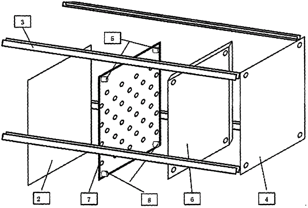
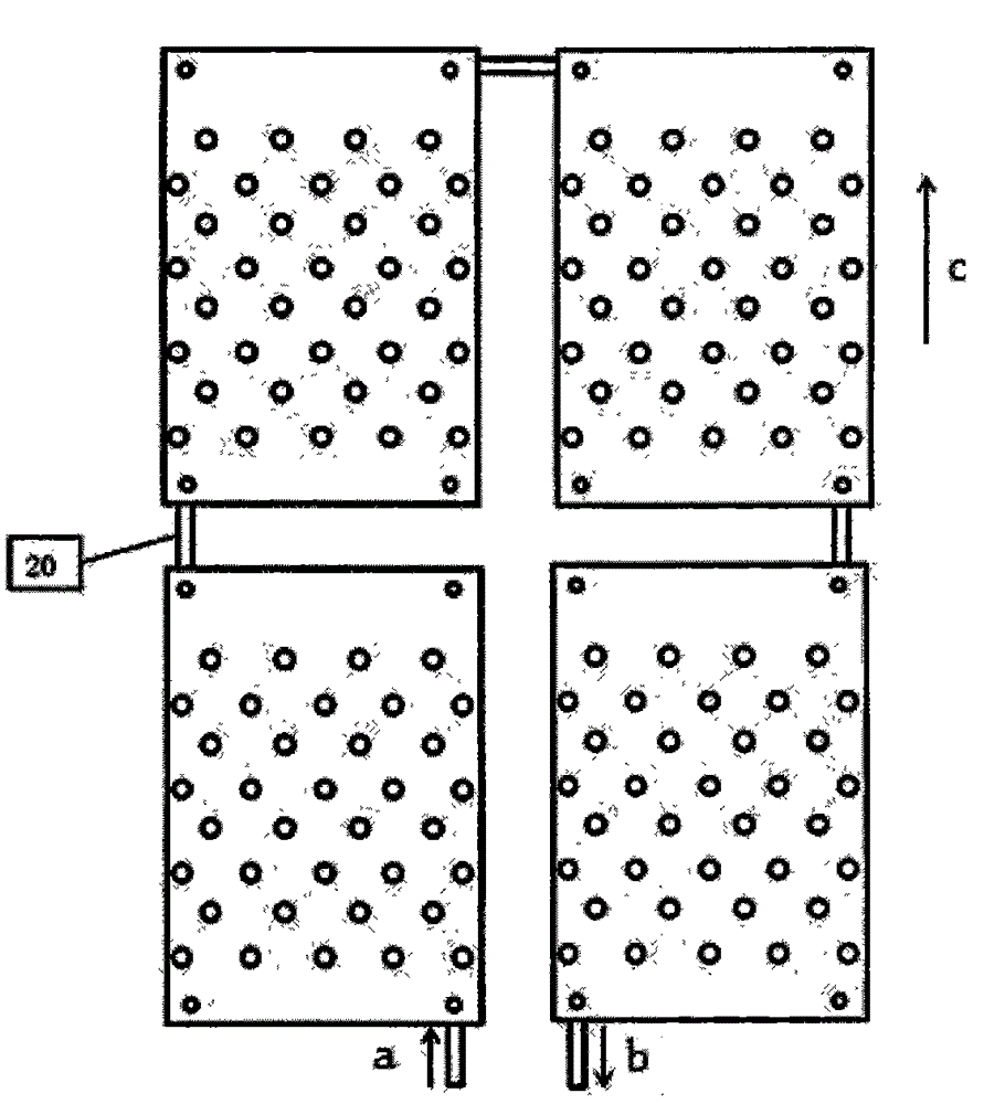
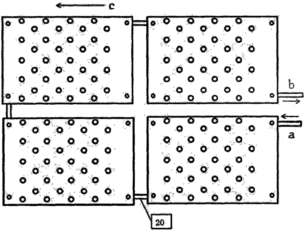
[0062] refer to Figure 1-17 , the heat-absorbing plate core 7 of the present invention is arranged in parallel by a smooth metal sheet 10 and a corrugated metal sheet 9, the outer surface of the smooth metal sheet 10 is coated with a composite solar heat-absorbing coating 11, and the inner surface of the corrugated metal sheet 9 is stamped and formed to guide Raised or ribbed12. In order to generate turbulent flow at a lower Reynolds number and improve the heat transfer efficiency of the heat-absorbing core 7, among the two metal sheets of the flat metal plate body, one is a non-corrugated flat sheet 10, and the other is stamped on the inner surface The corrugated thin plate 9 with flow-guiding protrusions or ribs 12 is formed.

[0063] The metal thin-plate heat-absorbing core 7 in the present invention does not u...


PUM


Abstract

The invention discloses a heat collecting plate core and a flat-plate type solar thermal collector. The flat-plate type solar thermal collector is characterized by comprising the heat collecting plate core based on a corrugated metal sheet structure, a superconductive hybrid heat transfer working medium, a transparent cover plate, a heat insulating material layer and an outer frame. The flat-plate type solar thermal collector has the characteristics of being compact in structure, high in heat transfer efficiency, small in pressure loss, light in weight, flexible to install, high in pressure bearing performance, resistant to freezing, scaling and corrosion, long in service life, low in cost and the like, and is very suitable for being combined with buildings. The superconductive hybrid heating medium serves as the heat transfer working medium, so that the solar thermal collector still operates normally at low temperature; the heat utilization efficiency is greatly improved; the use range is greatly enlarged; the application ways of the flat-plate type solar thermal collector are widened; the flat-plate type solar thermal collector is widely suitable for solar thermal collection occasions like civil buildings and industrial plants.

Description

technical field [0001] The invention belongs to the technical field of medium and low temperature solar heat collection, in particular to a heat absorbing plate core and a flat plate solar heat collector. Background technique [0002] Flat-plate solar collectors have been widely used in domestic water heating, swimming pool heating, industrial water heating, building heating and air conditioning and many other fields. The flat-plate solar collector is mainly composed of transparent cover plate, heat-absorbing plate core, heat insulation layer and shell frame, among which the plate-type heat-absorbing plate core is the core component of solar heat utilization. [0003] When the flat-plate solar collector is working, the solar radiation passes through the transparent cover and is projected on the heat-absorbing plate core, which is absorbed by the heat-absorbing plate core and converted into heat energy, and then the heat is transferred to the heat-absorbing plate core. The t...

Claims


Application Information

Patent Timeline
Patent Type & Authority Applications(China)
IPC IPC(8): F24J2/46F24J2/05F24J2/30F24S10/30F24S10/40
CPCY02B10/20Y02E10/44Y02P80/20
Inventor 孙红琴
Owner 孙红琴
Why Eureka
Try Eureka