A needle-free electrospinning device for porous materials

A porous material, electrospinning technology, used in textiles and papermaking, filament/thread forming, fiber processing, etc., can solve the problems of difficult control of spinning diameter, spinning sticking, etc. The effect of uniform yarn and improved spinning efficiency

Active Publication Date: 2017-04-19
CHINA FIRST AUTOMOBILE
View PDF1 Cites 0 Cited by
  • Summary
  • Abstract
  • Description
  • Claims
  • Application Information

AI Technical Summary

Problems solved by technology

However, the spinning produced by this needle-free spinning method will cause sticking, and the spinning diameter is not easy to control.

Method used


Image

  • A needle-free electrospinning device for porous materials
  • A needle-free electrospinning device for porous materials
  • A needle-free electrospinning device for porous materials

Examples


Embodiment 1

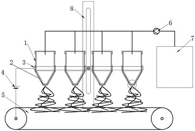
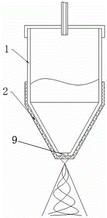
[0025] Mix and stir polyacrylonitrile (PAN), N,N dimethylformamide (NMP) and ethanol to form an 8wt% PAN solution; then add acetylacetone, stir evenly, add a certain amount of nano-silica powder and continue stirring until form a suspension, such as Figure 7 As shown, a porous copper foil with a pore size of 75 μm and a porosity of 45% is used as the porous medium 2, and it is matched with a 20ml spinning buffer tube 1, and the opening of the bottom end of the spinning buffer tube 1 is 8 mm, such as figure 2 As shown, wrap the porous medium 2 on the liquid outlet hole 9 at the bottom of the spinning buffer tube 1, install the spinning buffer tube 1 on the fixed copper core fixture 3, and wrap the porous medium on the spinning buffer tube 1 2. Closely contact with the inner surface of the 3 holes of the fixed copper core fixture to play the role of conducting voltage, and set the distance between spinning heads to 15cm. Such as figure 1 As shown, the solution is injected in...

Embodiment 2

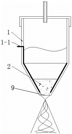
[0027] Configure 50wt% PVDF acetone solvent, add 2wt% water and mix to form spinning slurry. The size of the liquid outlet at the bottom is selected as a 20mm buffer cylinder, and the volume of the buffer cylinder is 200ml; powder metallurgy porous nickel is selected as the porous medium 2, with a porosity of 60%, a pore diameter of 100μm, and a thickness of 6mm. Such as image 3 As shown in the figure, when assembling, the copper conical electrode 1-1 is first inserted into the bottom of the spinning buffer tube 1, and the top end passes through the wall of the spinning buffer tube 1. Such as Figure 4As shown, the shape of the conical electrode 1-1 is the same as the shape of the bottom end of the spinning buffer tube 1, and plays the role of connecting the spinning solution in the spinning buffer tube 1 with the outer fixture. Afterwards, the porous medium 2 is cut into the same shape as the bottom of the spinning buffer cylinder 1, and placed into the liquid outlet hole ...


PUM

PropertyMeasurementUnit
diameteraaaaaaaaaa
pore sizeaaaaaaaaaa
pore sizeaaaaaaaaaa

Abstract

The invention relates to a porous material syringe needle-free static spinning apparatus characterized in that a spinning buffering cylinder of a spinning system is cylindrical; the upper and lower ends of the spinning buffering cylinder are conical; a liquid outlet is formed in the lower end of the spinning buffering cylinder; the diameter of the hole is 3 to 20mm; a porous medium sleeve is arranged on the lower end of the spinning buffering cylinder; the spinning buffering cylinder is connected with a power device via a copper core clamp; an outward extraction electrode of a copper core of the copper core clamp is connected with a power supplying system; an aperture formed in the top end of the spinning buffering cylinder is connected with a liquid discharging end of a liquid supplying device via a liquid supplying pipeline; a liquid charging end of the liquid supplying device is connected with a liquid storage case; and a receiving plate faces right under the liquid outlet formed in the lower end of the spinning buffering cylinder. Special spinning assemblies are employed, so spinning quality can be greatly improved and spinning evenness can be guaranteed; and the porous material syringe needle-free static spinning apparatus is characterized by simple technology, easy industrial application and wide application range.

Description

technical field [0001] The invention relates to a needle-free electrostatic spinning device for porous materials, which belongs to the electrostatic spinning technology. Background technique [0002] Electrospinning technology is a way of using high-voltage electrostatic action to make polymer solution or melt droplets point and generate jets. During the flight, the solvent evaporates or the melt solidifies to form nanofibers. It is divided into two spinning methods: needle type and needleless type. In order to improve the spinning efficiency, the usual needle type uses the multi-needle method for spinning, such as the "high-efficiency multi-needle electrospinning spinning device" with application number 200610157106.8. The liquid is pressed into multiple needles at the same time, and spun into filaments under the action of voltage. Needle electrospinning has the advantages of finer fineness and uniform product, but the efficiency of multi-needle spinning is still not high...

Claims


Application Information

Patent Timeline
Patent Type & Authority Patents(China)
IPC IPC(8): D01D5/00
Inventor 陈慧明姜涛张斌韩金磊常潇然张克金
Owner CHINA FIRST AUTOMOBILE
Why Eureka
Try Eureka