Sliding construction device and method for large-span arc-shaped roof

An arc-shaped, long-span technology, applied in the direction of construction, building structure, and building materials, can solve the problems of inconvenient construction methods and low safety factors, achieve ideal sliding speed, improve construction efficiency, and improve The effect of work efficiency

Active Publication Date: 2015-10-21
SHANGHAI GREENLAND CONSTR GRP
View PDF11 Cites 19 Cited by
  • Summary
  • Abstract
  • Description
  • Claims
  • Application Information

AI Technical Summary

Problems solved by technology

[0010] The purpose of the present invention is to solve the shortcomings and defects of the arc-shaped large-span roof construction method in the prior art, such as inconvenience and low safety factor, and provide a large-scale roof with mature method, safety and reliability, low technical difficulty and easy operation. The sliding construction method of the arc-span roof uses finite element structural analysis software to analyze the stress change of each rod according to the actual working conditions of each stage of installation, and compare it with the stress limit requirements of the design state to ensure that the construction stage The structure is safe and does not cause unfavorable additional stress. According to the reaction force of each support, the reaction force at the support frame and the force limit of the column and beam of the reinforced concrete structure analyzed by the software, the temporary support frame, sliding shoes, round Arc-shaped sliding steel box girder, arc-shaped sliding track and hydraulic jacking system, the jacking system is connected with hydraulic power station and PLC control system

Method used


Image

  • Sliding construction device and method for large-span arc-shaped roof
  • Sliding construction device and method for large-span arc-shaped roof
  • Sliding construction device and method for large-span arc-shaped roof

Examples


Embodiment Construction

[0024] The present invention will be further described below in conjunction with accompanying drawing, and the structure and principle of this device are very clear to those skilled in the art. It should be understood that the specific embodiments described here are only used to explain the present invention, not to limit the present invention.

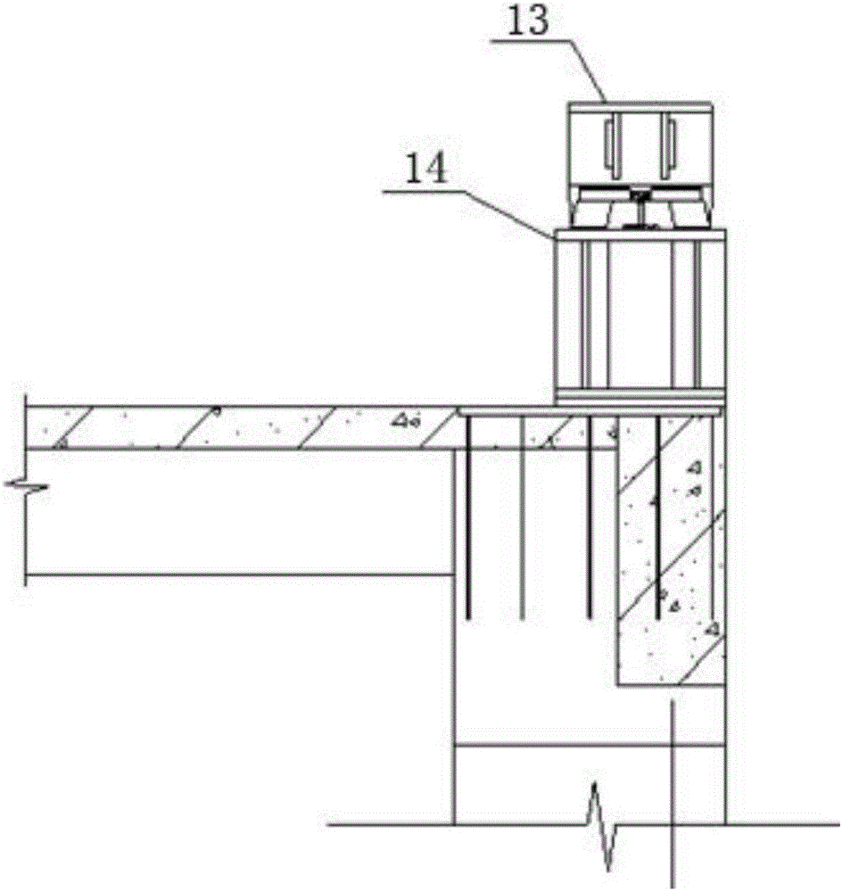
[0025] The present invention uses finite element structure analysis software to analyze the stress change of each member according to the actual working conditions of each stage of installation, and compares it with the stress limit requirement of the design state to ensure the structural safety of the construction stage without causing adverse additional stress. According to the reaction force of each support, the reaction force at the supporting tire frame, and the force limit of the column and beam of the reinforced concrete structure analyzed by the software, design the temporary supporting tire frame, sliding shoe, arc-shaped sli...


PUM


Abstract

The invention relates to the technical field of construction, in particular to a sliding construction device and method for a large-span arc-shaped roof. Finite element structural analysis software is adopted, the stress change of each rod piece is analyzed according to the actual condition of each installation stage, the stress change is compared with the stress limit value requirement of the design state to ensure structural safety in the construction stage, adverse additional stress can not be caused, and a temporary supporting jig frame, sliding shoes, an arc-shaped sliding steel box girder and a hydraulic pushing system are designed according to the reaction of each support, the reaction of the supporting jig frame and the column beam stress limit value of a reinforced concrete structure which are analyzed by the software. A pushing device controlled by a PLC works stably, the angular velocities of all pushing points are consistent, and the roof slides to the right position according to a predetermined movement path at an ideal sliding speed. Through the cooperation of various types of mechanical equipment, movement and hoisting are basically conducted within a small range, working efficiency is improved, and intersection construction with other professional construction sites is avoided.

Description

[technical field] [0001] The invention relates to the technical field of building construction, in particular to a large-span arc-shaped roof sliding construction device and construction method. [Background technique] [0002] The construction of large-span roofs in the prior art mainly adopts the construction methods of segmental assembly on the ground, mechanical hoisting on the ground, and segmental splicing at high altitude. [0003] The disadvantages of these traditional construction methods are: [0004] 1. There are many high-altitude splicing operations, and the safety risk is relatively large. [0005] 2. The splicing temporary support frame needs to be disassembled and assembled continuously with the progress of the installation, and the turnover workload is large. [0006] 3. Segmental splicing is completed at high altitude, and the workload at high altitude is heavy and the efficiency is low. [0007] 4. The weather is greatly affected, and the downtime in the...

Claims


Application Information

Patent Timeline
Patent Type & Authority Applications(China)
IPC IPC(8): E04G21/16
Inventor 陈学方叶绍铭厉宗标施仁华黄兵周金发阮治兵夏宗富黄杰
Owner SHANGHAI GREENLAND CONSTR GRP
Why Eureka
Try Eureka