Silver alloy sputtering target for forming electroconductive film, and method for manufacturing same

A technology of conductive film and manufacturing method, which is applied in the manufacture of semiconductor/solid-state devices, sputtering coating, circuits, etc., can solve the problems of increased sputtering and arc discharge times, and achieve the purpose of suppressing arc discharge, suppressing sputtering, Excellent durability effect

Active Publication Date: 2015-10-21
MITSUBISHI MATERIALS CORP
View PDF15 Cites 10 Cited by
  • Summary
  • Abstract
  • Description
  • Claims
  • Application Information

AI Technical Summary

Problems solved by technology

[0011] According to the silver alloy target for forming a reflective electrode film described in these patent documents 2 and 3, spattering can be suppressed even if a large power is applied. Increased, with a tendency to increase spatter based on arcing, requiring further improvement

Method used


Image

  • Silver alloy sputtering target for forming electroconductive film, and method for manufacturing same
  • Silver alloy sputtering target for forming electroconductive film, and method for manufacturing same
  • Silver alloy sputtering target for forming electroconductive film, and method for manufacturing same

Examples


Embodiment 1

[0085] Ag with a purity of 99.99% by mass or more and In, Sn, Sb, and Ga with a purity of 99.9% by mass or more as additive raw materials were prepared and charged in a high-frequency induction melting furnace built with a graphite crucible. The total mass at the time of melting was set at about 1100 kg.

[0086] When smelting, Ag is smelted first, and after Ag is melted, raw materials are added so as to obtain the target composition shown in Table 1, and the alloy molten metal is sufficiently stirred by the stirring effect by induction heating, and cast iron mold For casting.

[0087] The shrinkage cavity portion of the ingot obtained by this casting was cut off, and the surface in contact with the mold was removed by face cutting to obtain a cuboid ingot with an approximate size of 640×640×180 (mm) as a complete part.

[0088] This ingot was heated to 650° C., the rolling direction was changed on the way, and hot rolling was repeated several times until the plate thickness ...

Embodiment 2~21

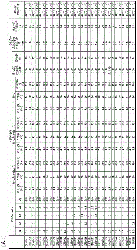
[0093] (Examples 2-21, Comparative Examples 1-11)

[0094] Same as Example 1, with the target composition shown in Table 1, the conditions of the passes from the last hot rolling pass to the first two passes in the finish hot rolling (rolling rate of each pass, strain rate, pass after pass) plate temperature), cooling rate after hot rolling, cold rolling conditions (total rolling rate of cold rolling, average value of all cold rolling passes of rolling rate of each pass, all cold rolling passes of strain rate The mean value in), and the conditions of heat treatment conditions (temperature, time) after cold rolling are carried out smelting, casting, hot rolling, cooling, cold rolling, after heat treatment, make embodiment 2~21 by rectification, machining, Targets of Comparative Examples 1-11. The cooling rates described in Table 1 are cooling by water spraying, and non-water cooling is cooling by only standing cooling.

[0095]

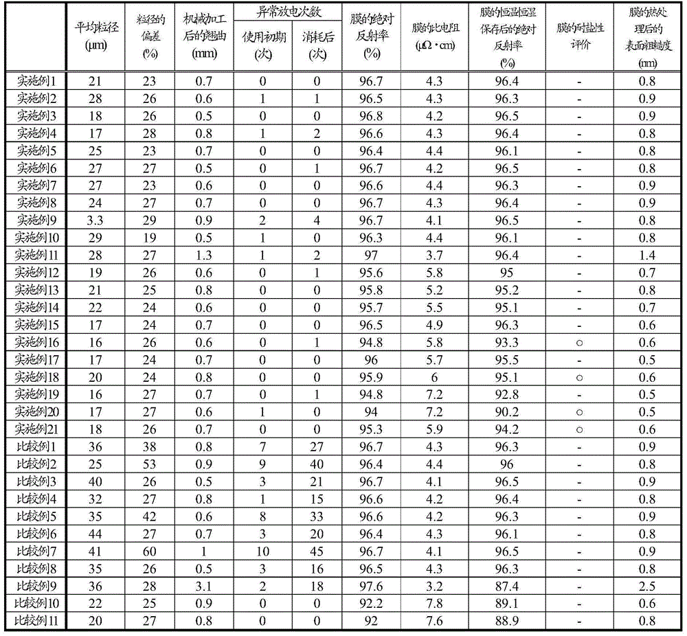
[0096] For the obtained target, the warpage...


PUM

PropertyMeasurementUnit
particle sizeaaaaaaaaaa
thicknessaaaaaaaaaa
thicknessaaaaaaaaaa

Abstract

A silver alloy sputtering target having a component composition containing a total of 0.1 to 1.5% by mass of In and/or Sn, which are elements that form a solid solution in Ag, with the remainder being made up by Ag and unavoidable impurities, the average grain diameter of the crystal grains being 1 μm to less than 30 μm, and fluctuations in the grain diameter of the crystal grains being no greater than 30% of the average grain diameter. The silver alloy sputtering target is manufactured by subjecting a melt-cast ingot to a hot rolling step, a cooling step, cold rolling, heat processing, and a machining processing step, in the stated order.

Description

technical field [0001] The present invention relates to a silver alloy sputtering target for forming conductive films such as reflective electrodes of organic EL elements and wiring films of touch panels, and a manufacturing method thereof. [0002] This application claims priority based on Patent Application No. 2013-048388 for which it applied in Japan on March 11, 2013, and uses the content here. Background technique [0003] The organic EL element is a light-emitting element in which a voltage is applied between the anode and the cathode formed on both sides of the organic EL light-emitting layer, holes are injected from the anode and electrons are injected from the cathode into the organic EL film, and used in The principle of light emission when holes and electrons combine in the organic EL light-emitting layer, and has attracted attention as a light-emitting element for display devices in recent years. There are passive matrix method and active matrix method in the d...

Claims


Application Information

Patent Timeline
Patent Type & Authority Applications(China)
IPC IPC(8): C23C14/34C22C5/06C22F1/00C22F1/14H01L51/50H05B33/10H05B33/26
CPCC23C14/3414C22C5/06C22F1/14H01L51/0021H10K71/60
Inventor 小见山昌三船木真一小池慎也奥田圣
Owner MITSUBISHI MATERIALS CORP
Why Eureka
Try Eureka