
Brake valve electro-hydraulic drive system with emergency shut valve function and brake valve

A drive system and gate valve technology, applied in the field of gate valve electro-hydraulic drive system and gate valve, can solve problems such as oil cylinder or structure suffocation, accumulator filling, fault self-diagnosis, etc., to prevent water hammer phenomenon, system layout is convenient, The effect of preventing overload

Active Publication Date: 2015-10-28
HUNAN SHANYUANAN AUTOMATIC CONTROL SYST
View PDF8 Cites 18 Cited by
  • Summary
  • Abstract
  • Description
  • Claims
  • Application Information

AI Technical Summary

Problems solved by technology

[0003]Patents CN202012516U and CN201110057860 "A Hydraulic Actuator for Coal Mine Automatic Drainage", existing problems: 1. Although the emergency opening / closing power problem has been solved, it cannot Realize that the actuator can fill the accumulator at any position, and the accumulator can be filled only after the oil cylinder is extended or retracted to the end, which greatly limits the function expansion of the mechanism. For example, when the gate valve is kept half-open, When it is necessary to fill the accumulator with liquid, it cannot be implemented; 2. There is no system detection and alarm, fault self-diagnosis function, high reliability requirements for safety emergency equipment, and real-time dynamic detection and judgment cannot be provided whether the charging pressure of the emergency accumulator meets the requirements; 3. According to the two principles provided by it, the emergency function is only effective when the electromagnet is energized, and what is needed should be the emergency valve closing function in the event of a power failure; 4. The double-bar drive is prone to asynchrony and thus The problem of causing damage to the cylinder or structure is not practical in actual use
[0005]Patent CN201110075968 "A Mining Submersible Electro-hydraulic Control Gate Valve" uses a bidirectional gear pump to drive the oil cylinder to open and close the gate valve. The control is simple, but there is no emergency function

Method used


Image

  • Brake valve electro-hydraulic drive system with emergency shut valve function and brake valve

Examples


Embodiment Construction

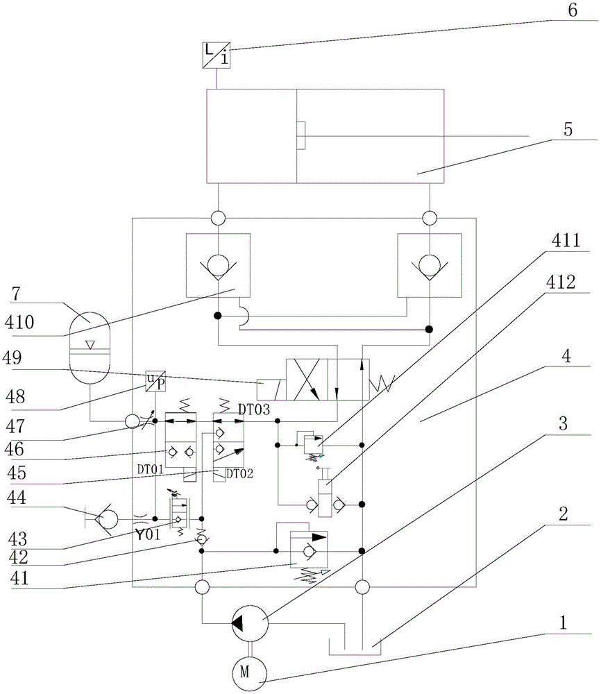
[0031] The present invention is described in detail below in conjunction with accompanying drawing, as figure 1 As shown, a gate valve electro-hydraulic drive system with emergency valve closing function includes a motor 1, a hydraulic pump 3, an integrated control valve 4, an actuator cylinder 5, an accumulator 7, and a hydraulic oil tank 2;

[0032] The integrated control valve 4 includes: oil supply overflow valve 41, check valve 42, normally closed two-position two-way proportional directional valve 43, pressure measuring joint 44, two-position three-way electromagnetic ball valve 45, normally open two-position Two-way electromagnetic ball valve 46, adjustable flow valve 47, pressure sensor 48, two-position four-way electromagnetic reversing valve 49, two-way hydraulic lock 410, overflow valve 411, manual pump 412;

[0033] The hydraulic pump 3 is a gear pump, and the hydraulic pump 3 is driven by the motor 1. The oil suction port of the hydraulic pump 3 is connected with ...


PUM


Abstract

The invention discloses a brake valve electro-hydraulic drive system with an emergency shut valve function and a brake valve. The brake valve electro-hydraulic drive system includes a motor, a hydraulic pump, an integrated control valve, an actuating cylinder, an energy accumulator and a hydraulic oil tank, and is mainly characterized in that the system has the energy accumulator emergency function; the system works in two modes, namely, a speed regulating mode and a normal mode; when the system works in the speed regulating mode, the energy accumulator has a medium energy storage function when working normally, so that the motor power can be effectively reduced, and the speed of a switch is higher; the system has the self-diagnostic function, is safe and reliable, and can judge whether the system is working normally or not according to the real-time signals detected by a pressure sensor; the system integrates the manual emergency function, and when no power is provided, the valve can be manually opened and closed repeatedly.

Description

technical field [0001] The invention belongs to the technical field of mine drainage, and in particular relates to an electro-hydraulic drive system for a gate valve with an emergency valve closing function and a gate valve. Background technique [0002] Due to its simple structure and good sealing performance, gate valves are widely used in water supply and drainage systems such as mines. The most common gate valve actuators on the market are handwheel switches. With the development of gate valves towards high pressure, large diameter and automation. Handwheel switch actuators can no longer meet the demand. At present, there is an electric execution scheme, which replaces the handwheel mechanism through the rotation of the motor and the torque increase of the reducer. On the one hand, it can reduce labor intensity, and on the other hand, it is easy to realize remote control; but there are many problems: mainly the load It is difficult to start, and overload protection is...

Claims


Application Information

Patent Timeline
IPC IPC(8): F16K31/04F16K37/00F16K47/02F16K31/124
CPCF16K31/04F16K31/1245F16K37/0041F16K47/023
Inventor 张银辉
Owner HUNAN SHANYUANAN AUTOMATIC CONTROL SYST
Learn More