
Bio-electrical signal sensor and method using sensor for manufacturing electric signal collecting device

A bioelectrical signal and acquisition device technology, applied in sensors, applications, medical science, etc., can solve problems such as pain and discomfort, and achieve the effects of stable electrode impedance, high measurement accuracy, and improved utilization

Active Publication Date: 2015-11-04
SUZHOU GREENTEK
View PDF8 Cites 15 Cited by
  • Summary
  • Abstract
  • Description
  • Claims
  • Application Information

AI Technical Summary

Problems solved by technology

[0006] The purpose of the present invention is to overcome the pain and discomfort of the receptors caused by the prior art, and provide a bioelectrical signal sensor with a reasonable structure. The electrode head is provided with a plurality of flexible columnar tubes, and the middle part of the columnar tubes It has a porous permeable core, the electrode and the skin are in good contact with the electrolyte, the impedance is stable, the measurement accuracy is high, and the wearing comfort is improved; a method for making an electrical signal acquisition device using the bioelectrical signal sensor of the present invention is also provided

Method used


Image

  • Bio-electrical signal sensor and method using sensor for manufacturing electric signal collecting device
  • Bio-electrical signal sensor and method using sensor for manufacturing electric signal collecting device
  • Bio-electrical signal sensor and method using sensor for manufacturing electric signal collecting device

Examples


Embodiment 1

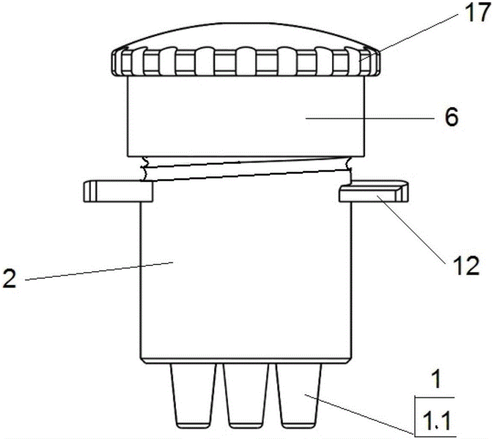
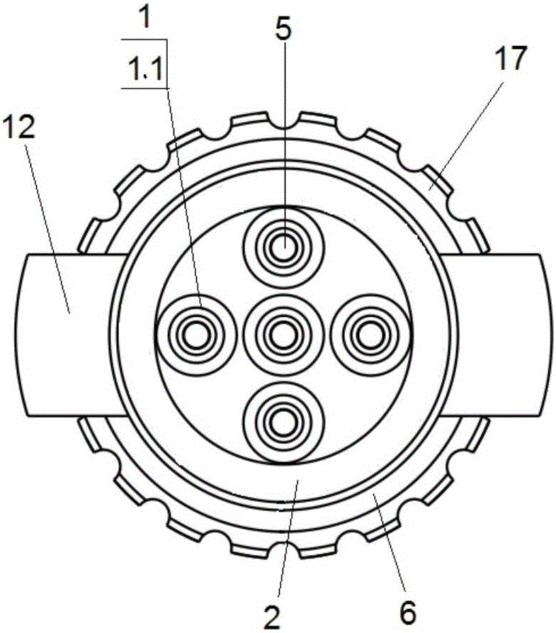
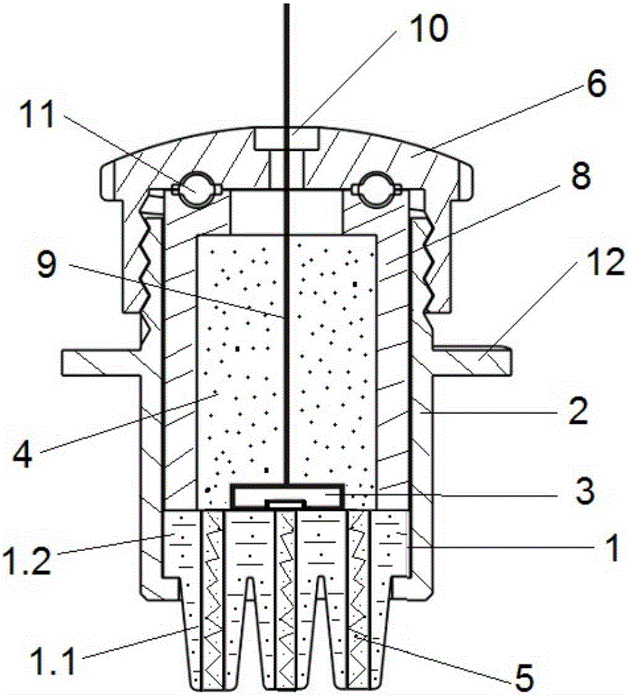
[0044] Example 1: is a basic embodiment of the present invention. As shown in the drawings, a bioelectrical signal sensor includes an electrode head 1 with a columnar tube 1.1 and a connecting body 1.2, an electrode body 2 with a cavity, a seal at the upper end of the cavity, and an electrolyte 4 filled in In the fixed tube 8 in the cavity of the electrode body 2 or in the seal or directly in the cavity, the electrode 3 is connected to the electrolyte 4; the electrode head 1 is made of flexible material, and one end is provided with a plurality of The other end of the cylindrical tube 1.1 on the measured surface is sealed and fixed with the lower end of the cavity of the electrode body 2; the middle part of the cylindrical tube 1.1 is provided with an electrolyte permeable core 5 with micropores for allowing the electrolyte 4 to penetrate to the end of the cylindrical tube 1.1 through the micropores department.

Embodiment 2

[0045] Example 2: is a further example. like Figure 1-8 As shown, on the basis of Embodiment 1, the detachable sealed and fixed connection between the sealing member and the electrode body 2 of the bioelectric signal sensor is a threaded connection. There is also a positioning piece 12 on the outer periphery of the electrode body 2 . The columnar tube 1.1 is cylindrical or tapered; there are at least two columnar tubes 1.1, and they are evenly distributed on the end face of the end face of the electrode head 1 centered on the centroid. The inner wall of the electrode body 2 or / and the column body 7.1 of the sealing column 7 or / and the fixed tube 8 is a rough surface. The inner wall has a rough surface, which is conducive to coating or electroplating conductive coating, increasing the adhesion of the conductive coating and prolonging the service life. The electrode 3 is a conductor soaked in the electrolyte 4, or a conductive layer 13, the conductive layer 13 is the inner...

Embodiment 3

[0046] Example 3: is a further example. like image 3 As shown, on the basis of Embodiment 1, the bioelectric signal sensor, the seal at the upper end of the cavity of the electrode body 2 is a sealing cover 6; the sealing cover 6 and the electrode body 2 are detachably sealed and fixedly connected; The electrode head 1 and the lower end of the electrode body 2 cavity are sealed and fixed. The shoulder of the connecting body 1.2 of the electrode head 1 is embedded in the hole at the lower end of the electrode body 2 cavity, and the sealing cover 6 presses the fixed tube 8 in the electrode body 2 , the fixed tube 8 is pressed on the upper plane of the electrode head 1; the fixed tube 8 is a hollow tube, and the electrolyte 4 is filled in the tube. The sealing cover is made of soft rubber. The detachable sealed and fixed connection between the sealing cover 6 and the electrode body 2 is a threaded connection, and can also be a tight fit connection or snap connection.

[004...


PUM


Abstract

The invention relates to a bio-electrical signal sensor and a method using the sensor for manufacturing an electric signal collecting device. The sensor comprises an electrode tip provided with columnar tubes and a connecting body, an electrode body provided with a cavity, and electrolytes. A sealing part is arranged at the upper end of the cavity. An electrode is communicated with the electrolytes. The electrode tip is made of a flexible material. Electrolyte permeation cores with tiny holes are arranged in the middles of the columnar tubes. The manufacturing method for the collecting device comprises the steps that the electrical signal sensor is installed, and one ends of supporting bands penetrate into connecting holes in fixing blocks; or furthermore, multiple signal electrical signal collecting devices are combined to form a combined type electrical signal connecting device matched with an organism. The bio-electrical signal sensor has the advantages that the sensor is reasonable in structure and easy to manufacture, and the electrode tip can be replaced; as the porous permeation cores mutually independent are arranged in the middles of the flexible columnar tubes of the electrode tip, the electrode makes good contact with skin, electrode impedance is stable, the measurement precision is high, and wearing comfort is improved.

Description

technical field [0001] The present invention relates to a bioelectrical signal sensor and its method for making an electrical signal acquisition device. The bioelectrical signal sensor is widely used in bioelectricity recording, measurement, and stimulation, including medical equipment, mobile equipment, home health care, psychological recognition, etc. Knowledge, games, brain-computer interface, rehabilitation training, neuromarketing, etc., especially for glue-free bioelectric measurement and wearable devices. Background technique [0002] With the development of science and technology, bioelectricity (such as EEG, ECG, EMG, etc.) measurement has been widely used in the monitoring and diagnosis of various nervous system diseases, and rehabilitation equipment for bioelectrical feedback. EEG measurement is also an important experimental method in cognitive psychology research. In order to obtain accurate weak EEG signals, good contact between the electrodes and the scalp is...

Claims


Application Information

Patent Timeline
Patent Type & Authority Applications(China)
IPC IPC(8): A61B5/04
Inventor 段晏文李广利樊安生
Owner SUZHOU GREENTEK
Learn More