Wave energy power generation system maximum power tracking device and control method

A technology of maximum power tracking and power generation system, applied in the direction of synchronous generator control, control system, control generator, etc., can solve problems such as program misjudgment, high objective function requirements, oscillation and so on

Inactive Publication Date: 2015-11-04
NORTH CHINA ELECTRIC POWER UNIV (BAODING)
View PDF3 Cites 9 Cited by
  • Summary
  • Abstract
  • Description
  • Claims
  • Application Information

AI Technical Summary

Problems solved by technology

The hill-climbing search algorithm does not need to measure the wave height and wave period, nor does it need to know the power characteristics of the specific wave energy absorbing mechanism in advance, but applies artificial speed disturbance, and then automatically searches for the optimal load point of the generator by measuring the power change. Because the tracking step size cannot balance the tracking accuracy and response speed, sometimes the "misjudgment" and oscillation phenomenon of the program during operation will occur
The optimal gradient method is a numerical calculation method for multi-dimensional unconstrained optimization problems based on the gradient method, but the solution obtained by the iteration of the optimal gradient method may be a local optimal solution rather than a global optimal solution; The objective function is more demanding

Method used


Image

  • Wave energy power generation system maximum power tracking device and control method
  • Wave energy power generation system maximum power tracking device and control method
  • Wave energy power generation system maximum power tracking device and control method

Examples


Embodiment Construction

[0070] The preferred embodiments will be described in detail below in conjunction with the accompanying drawings. It should be emphasized that the following description is illustrative only and not intended to limit the scope of the invention and its application.

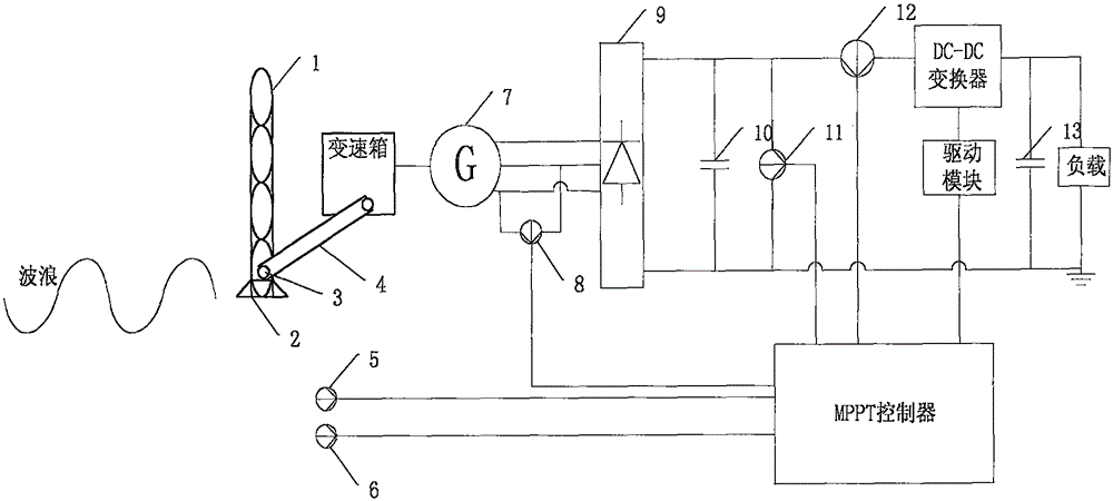
[0071] figure 1 It is a hardware structure diagram of the embodiment of the present invention, wherein, the main parameters of the permanent magnet synchronous generator 7 are: the rated power is 300W, the rated voltage is 24V, the rated speed is 800r / min, and the main parameters of the maximum power tracking device are: MPPT controller Adopt dsPIC33FJ16GS504 microcontroller, DC-DC converter adopts Boost circuit, drive module adopts MCP14E3, voltage sensor 11 adopts LV28-P, current sensor 12 adopts LA25-NP, speed sensor 6 adopts ZLS-PX, speed sensor 8 adopts voltage zero-crossing detection type frequency meter, the first capacitor C1 = 10uF, the second capacitor C2 = 100uF.

[0072] Acquisition of training samples...


PUM


Abstract

The invention belongs to the field of wave energy power generation, and particularly relates to a wave energy power generation system maximum power tracking device and a control method. The device comprises a swing plate, a pedestal, a rotating shaft, a chain, a gear box, a permanent magnet synchronous power generator, a rectifier, a DC/DC converter, an MPPT controller, a speed sensor, a voltage sensor, a current sensor, a water level sensor, a rotating speed sensor, a first capacitor, a second capacitor, a driving module and a load. The speed sensor, the water level sensor and the rotating speed sensor which are arranged in front of the swing plate for 2m and arranged at the same horizontal plane with the center of gravity of the swing plate are installed to acquire work vectors, and large number of actual samples of work vector-optimal work voltage are acquired and a work vector-optimal work voltage prediction model is established by utilizing a support vector machine. Maximum power tracking is performed via combination of the prediction model and a small-step disturbance observation method, and power generation efficiency of a wave energy power generation system can be effectively enhanced.

Description

technical field [0001] The invention belongs to the field of wave energy power generation, and in particular relates to a maximum power tracking device and a control method of a wave energy power generation system. Background technique [0002] As the global energy crisis continues to intensify, the greenhouse effect continues to strengthen, and the air quality continues to decline, countries are paying more and more attention to the development of new energy, especially wave power generation. With the continuous decline in the cost of wave power generation, in the future wave energy It will surely replace traditional energy and become a stable energy solution in the future. [0003] The important feature of waves is multi-dimensional and random motion, which has a high degree of inhomogeneity in spatial distribution and randomness in time without rules to follow. At present, there are few studies on the optimal power point of wave energy generation system. Some researcher...

Claims


Application Information

Patent Timeline
Patent Type & Authority Applications(China)
IPC IPC(8): H02P9/00H02P101/00H02P103/20
Inventor 何宗源王印松马良玉刘长良刘卫亮林永君马永光
Owner NORTH CHINA ELECTRIC POWER UNIV (BAODING)
Why Eureka
Try Eureka