Improved filament welding machine

A welding machine and filament technology, applied in the field of machinery, can solve problems such as low work efficiency, high labor costs, and low degree of automation, and achieve the effect of not being easy to misuse, not easy to loosen, and firmly clamped

Active Publication Date: 2015-11-11
邳州市鑫盛创业投资有限公司
View PDF5 Cites 1 Cited by
  • Summary
  • Abstract
  • Description
  • Claims
  • Application Information

AI Technical Summary

Problems solved by technology

[0002] Filaments, especially those of halogen lamps, need to weld molybdenum strips and tantalum strips at one end of the tungsten wire as leads. Since the molybdenum strips, tantalum strips, and tungsten wires are all small objects, when preparing filaments, the scrap rate is high. The efficiency is low, and the size and shape of the prepared filaments are quite different, which seriously affects the service life of the filament and the accuracy of the power of the halogen lamp.
[0003] A Chinese patent application number (200710092753.X) discloses a production device for a multi-station continuous electric lamp cap filament component, which is characterized in that it consists of a frame, a turntable arranged on the frame, and a turntable arranged on the turntable. Filament foot clips, filament foot clamping mechanism distributed next to the turntable, molybdenum sheet welding mechanism, tantalum sheet welding mechanism, improved filament welding mechanism, filament component unloading mechanism, power transmission device that drives the turntable to rotate, control power transmission device , The clamping mechanism of the filament foot, the molybdenum sheet welding mechanism, the tantalum sheet welding mechanism, the improved filament welding mechanism, and the filament member unloading mechanism are composed of an electronic control device that operates according to the program. The production device has a low degree of automation and high labor costs. As a result, its production efficiency and production quality are difficult to meet the requirements of market competition

Method used


Image

  • Improved filament welding machine
  • Improved filament welding machine
  • Improved filament welding machine

Examples


Embodiment Construction

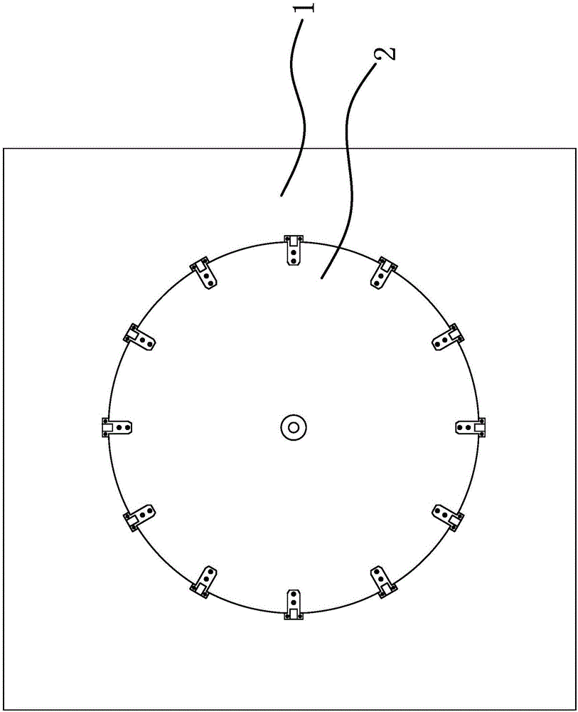
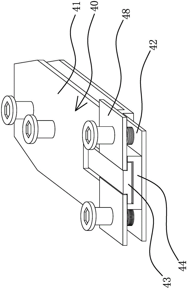
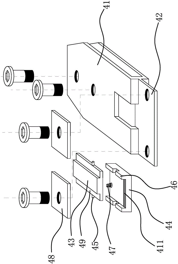
[0039] Such as figure 1 and Figure 4 As shown, the improved filament welding machine includes a base 1, a turntable 2 is arranged on the base 1, a stepping motor 3 is arranged between the turntable 2 and the base 1 to drive the turntable 2 to rotate, and the periphery of the turntable 2 is uniformly distributed with Several clamping structures, the base 1 is provided with a molybdenum belt feeding device, a first soldering device, a tantalum tape welding device, a second soldering device, a tungsten wire welding device and a filament blanking device, and a molybdenum belt feeding device, a second A soldering device, a tantalum strip soldering device, a second soldering device, a tungsten wire soldering device and a filament feeding device are distributed on the periphery of the turntable 2 in sequence. The molybdenum strip is tightly pressed in the clamping structure, and the preparation of the filament is completed through the processes of fluxing, tantalum strip welding, f...


PUM


Abstract

The invention provides a filament welding machine, and belongs to the technical field of machinery. The filament welding machine solves the technical problems of low automation degree, poor welding quality and the like of an existing filament welding machine. The filament welding machine comprises a base, a rotating disc is arranged on the base, a stepping motor driving the rotating disc to rotate is arranged between the rotating disc and the base, a plurality of clamping devices are uniformly and circumferentially distributed at the edge of the rotating disc, the base is provided with a molybdenum strip feeding device, a first weld-aid device, a tantalum strip welding device, a second weld-aid device, a tungsten filament welding device and a filament discharging device, and the molybdenum strip feeding device, the first weld-aid device, the tantalum strip welding device, the second weld-aid device, the tungsten filament welding device and the filament discharging device are sequentially distributed on the periphery of the rotating disc. The filament welding machine has the advantages of high automation degree and welding quality and the like.

Description

technical field [0001] The invention belongs to the technical field of machinery and relates to an improved filament welding machine. Background technique [0002] Filaments, especially those of halogen lamps, need to weld molybdenum strips and tantalum strips at one end of the tungsten wire as leads. Since the molybdenum strips, tantalum strips, and tungsten wires are all small objects, when preparing filaments, the scrap rate is high. The efficiency is low, and the size and shape of the obtained filaments vary greatly, which seriously affects the service life of the filament and the accuracy of the power of the halogen lamp. [0003] A Chinese patent application number (200710092753.X) discloses a production device for a multi-station continuous electric lamp cap filament component, which is characterized in that it consists of a frame, a turntable arranged on the frame, and a turntable arranged on the turntable. Filament foot clips, filament foot clamping mechanism distr...

Claims


Application Information

Patent Timeline
Patent Type & Authority Applications(China)
IPC IPC(8): B23K37/02B23K37/053B23K37/00
CPCB23K11/002B23K11/31B23K11/36B23K37/00B23K37/02B23K37/0435B23K37/053H01K3/28
Inventor 张德强
Owner 邳州市鑫盛创业投资有限公司
Why Eureka
Try Eureka