Spray non-woven spinning device and spray non-woven spinning method for producing micro-nanofibers

A micro-nano fiber, non-woven technology, used in fiber processing, textile and papermaking, filament/thread forming, etc., to achieve the effects of easy operation, fine fiber diameter, and good fiber web uniformity

Active Publication Date: 2015-11-11
SHANGHAI UNIV OF ENG SCI
View PDF3 Cites 6 Cited by
  • Summary
  • Abstract
  • Description
  • Claims
  • Application Information

AI Technical Summary

Problems solved by technology

At present, there is no method and apparatus for alternati

Method used


Image

  • Spray non-woven spinning device and spray non-woven spinning method for producing micro-nanofibers
  • Spray non-woven spinning device and spray non-woven spinning method for producing micro-nanofibers
  • Spray non-woven spinning device and spray non-woven spinning method for producing micro-nanofibers

Examples


Embodiment 1

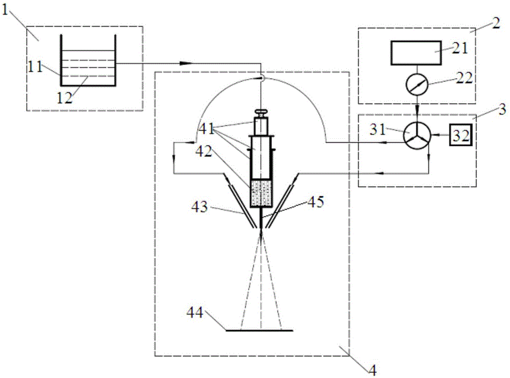
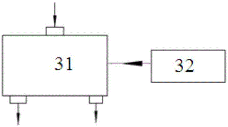
[0040] A device for producing liquid jet nonwoven spinning of micro-nano fibers, such as figure 1As shown, it includes a polymer solution input unit 1 , an air flow input unit 2 , an alternating jet flow generating unit 3 and a liquid jet nonwoven spinning unit 4 . The polymer solution input unit 1 is a solution container 11 for containing the polymer solution 12, and its function is to provide the solution raw material for liquid jet spinning. The air flow input unit 2 includes an air source 21 and a pressure gauge 22, and its function is to provide air with a constant pressure jet source. The liquid jet nonwoven spinning unit 4 is respectively connected with the polymer solution input unit 1 and the alternating jet flow generating unit 3, and the alternating jet flow generating unit 3 is also connected with the airflow input unit 2, and the liquid jet nonwoven spinning unit 4 includes a solution pressure pushing device 41, a solution storage chamber 42, an air jet tank 43, ...

Embodiment 2

[0052] Polyethylene oxide (PEO) was dissolved in distilled water, and a solution with a concentration of 7% was prepared by stirring and heating. Regulate air pressure valve, allow pressure value 0.26Mpa, the internal diameter of spinneret hole is 0.4 millimeter, start spinning, the final fiber diameter that the spinning of ejection forms under the situation that does not use device of the present invention (continuous air flow) is 0.5 Micron.

Embodiment 3

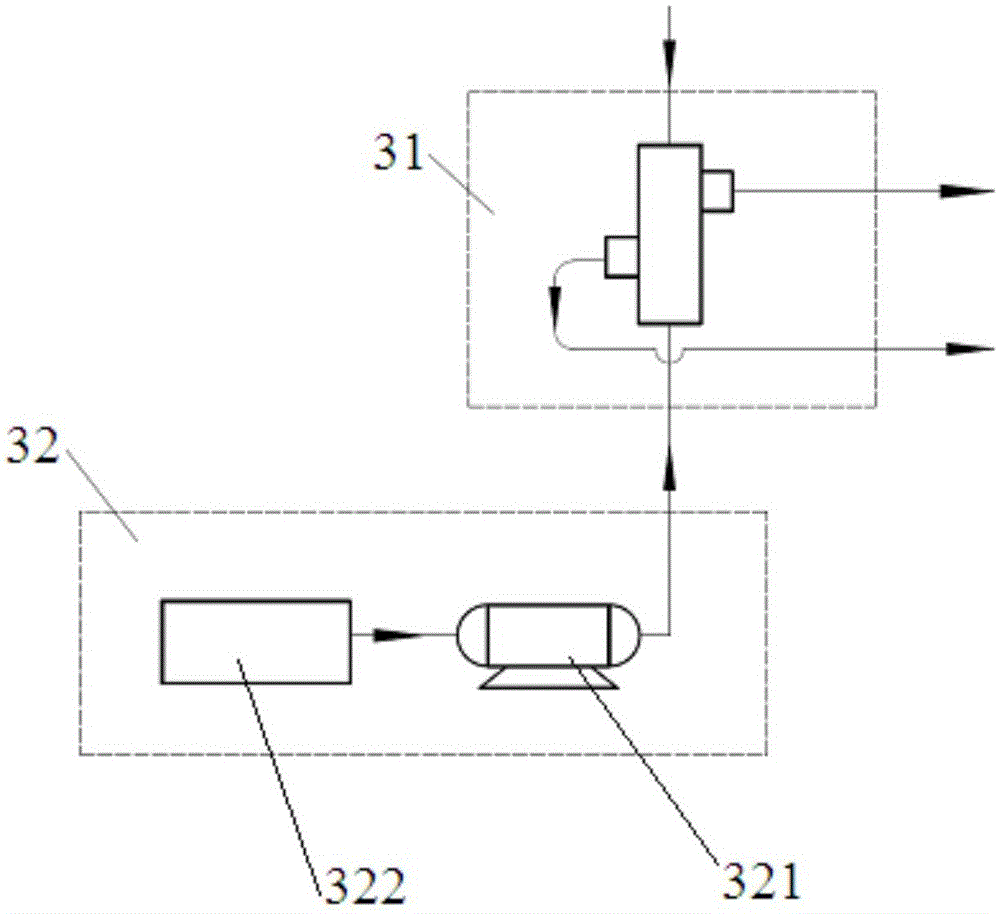
[0054] Liquid jet nonwoven spinning with alternating jet frequency of 1 Hz (using such as Figure 4 Alternating jet generator shown).

[0055] According to the concentration of the solution in Example 2, the pressure and the diameter of the spinneret hole are set, and the speed value of 60 revolutions per minute is input into the PC controller, then an alternating jet with a frequency of 1 Hz can be obtained from the air flow output part, and then the pipes are respectively opened for air flow input The part, the alternating jet flow generating part and the variable frequency motor, start spinning, receive the fiber, and measure the fiber diameter to obtain a final fiber diameter of 0.46 microns.


PUM

PropertyMeasurementUnit
Diameteraaaaaaaaaa

Abstract

The invention relates to a spray non-woven spinning device and a spray non-woven spinning method for producing micro-nanofibers. The spray non-woven spinning method comprises the following steps: firstly, making up polymer solution; setting a frequency parameter of alternating jet flow; injecting the solution into a solution storage chamber; turning on an airflow inlet unit; then, turning on a polymer solution inlet unit; extruding solution trickles from spinning orifices; congealing the sprayed solution trickles to a spinning receiving net forming device under the tensile impact of the alternating jet flow generated by an alternating jet flow generation unit to form a fiber net. Compared with the prior art, the spray non-woven spinning device achieves the goal that final fibers are further refined through the resonance action generated by the alternating jet flow, therefore the fibers are thinner in diameter, and the fiber net is better in evenness; the spray non-woven spinning device has another characteristic of being more energy-saving and environmental friendly, and the operation is convenient.

Description

technical field [0001] The invention belongs to the field of making micro-nano fibers, and in particular relates to a liquid-jet non-woven spinning device and method for producing micro-nano fibers. Background technique [0002] Liquid jet nonwoven spinning technology is a new spinning technology. This technology uses polymer solution as a raw material, and uses high-speed air jets to impact the fine stream of polymer solution extruded from the spinneret hole, so that the diameter of the thin stream of solution is rapidly reduced, and the solvent is quickly volatilized to become micro-nano fibers, which are condensed in A web is formed on a receiving device. Liquid jet nonwoven spinning web technology was produced in 2009, which is a technology between melt blown nonwoven spinning web technology and electrospinning web technology. For some polymers that cannot be spun by melt-blown technology, such as polymers with high melting point or easily degraded at high temperature,...

Claims


Application Information

Patent Timeline
IPC IPC(8): D01D5/00
Inventor 辛三法王磊磊王泽凡盛寒杨一帆钱晓东
Owner SHANGHAI UNIV OF ENG SCI
Why Eureka
Try Eureka