High-power long-wave infrared 8 micron-12 micron laser device based on polarization beam combination technology
A long-wave infrared and polarization beam combining technology, which is applied in the field of laser applications, can solve the problems of low conversion efficiency of a single optical parametric oscillator and difficulty in obtaining high output power of a single resonant cavity, and achieve the effect of improving the light-to-light conversion efficiency
- Summary
- Abstract
- Description
- Claims
- Application Information
AI Technical Summary
Problems solved by technology
Method used
Image
Examples
specific Embodiment approach 1
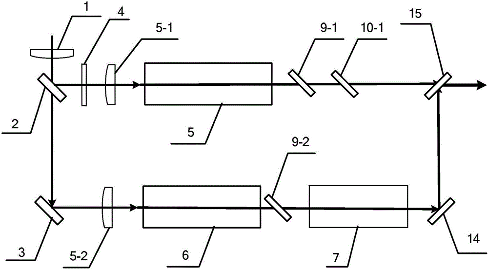
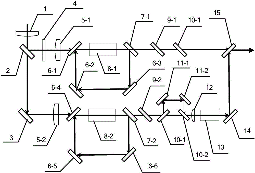
[0035] Specific implementation mode 1, refer to figure 1 and figure 2 Describe this embodiment in detail. The high-power long-wave infrared 8 μm to 12 μm laser based on polarization beam combining technology described in this embodiment includes No. 1 coupling system 5-1, No. 2 coupling system 5-2, and No. 3 coupling system 1. Beam splitter 2. No. 1 mirror 3. 1 / 2 wave plate 4. No. 1 ZnGeP 2 Optical parametric oscillator 5, No. 2 ZnGeP 2 Optical parametric oscillator 6, No. 1 plane mirror 9-1, No. 2 plane mirror 9-2, No. 3 plane mirror 10-1, ZnGeP2 optical parametric amplifier 7, No. 1 reflector 14 and polarizer 15;
[0036] A beam of 2.1 μm pulsed laser is vertically incident on the No. 3 coupling system 1, and after the beam conversion by the No. 3 coupling system 1, it enters the beam splitter 2 at an incident angle of 45°, and is divided into two beams by the beam splitter 2. It is horizontally polarized 2.1μm laser;
[0037] A beam of horizontally polarized 2.1 μm las...
specific Embodiment approach 2
[0042] Specific Embodiment 2. This specific embodiment is a further description of the high-power long-wave infrared 8 μm to 12 μm laser based on polarization beam combining technology described in specific embodiment 1. In this embodiment, No. 1 ZnGeP 2 The optical parametric oscillator 5 includes No. 4 plane mirror 6-1, No. 5 plane mirror 7-1, No. 2 reflector 6-2, No. 3 reflector 6-3 and No. 1 ZnGeP2 crystal 8-1;
[0043] After being converted by the No. 1 coupling system 5-1, it is incident on the No. 1 ZnGeP 2 The No. 4 plane mirror 6-1 of the optical parametric oscillator 5 has an incident angle of 45°. After being transmitted by the No. 4 plane mirror 6-1, it is incident on the No. 1 ZnGeP2 crystal 8-1, and passes through the No. 1 ZnGeP2 crystal 8-1 at 45 °. The incident angle enters the No. 5 plane mirror 7-1, and is reflected and transmitted by the No. 5 plane mirror 7-1;
[0044] After being reflected by No. 5 plane mirror 7-1, it is incident on No. 3 reflector 6-3 ...
specific Embodiment approach 3
[0047] Specific Embodiment 3. This specific embodiment is a further description of the high-power long-wave infrared 8 μm ~ 12 μm laser based on the polarization beam combining technology described in specific embodiment 1. In this embodiment, No. 2 ZnGeP 2 Optical parametric oscillator 6 comprises No. 6 plane mirror 6-4, No. 7 plane mirror 7-2, No. 4 reflector 6-5, No. 5 reflector 6-6 and No. 2 ZnGeP2 crystal 8-2;
[0048] The beam is transformed by the No. 2 coupling system 5-2 and then incident on the No. 2 ZnGeP 2 The No. 6 plane mirror 6-4 in the optical parametric oscillator 6 is incident to the No. 2 ZnGeP2 crystal 8-2 after being transmitted by the No. 6 plane mirror 6-4; No. plane mirror 7-2, reflected and transmitted through No. 7 plane mirror 7-2;
[0049] After being reflected by No. 7 plane mirror 7-2, it is incident on No. 5 reflector 6-6 at an incident angle of 45°; after being reflected by No. 5 reflector 6-6, it is incident on No. 4 reflector 6-5 at an incide...
PUM
 Abstract
Description
Claims
Application Information
 - R&D
- Intellectual Property
- Life Sciences
- Materials
- Tech Scout
- Unparalleled Data Quality
- Higher Quality Content
- 60% Fewer Hallucinations
Browse by: Latest US Patents, China's latest patents, Technical Efficacy Thesaurus, Application Domain, Technology Topic, Popular Technical Reports.
© 2025 PatSnap. All rights reserved.Legal|Privacy policy|Modern Slavery Act Transparency Statement|Sitemap|About US| Contact US: help@patsnap.com


