Side emitting device

A side and emitting surface technology, applied in the field of side emitting devices, can solve the problems of poor coupling efficiency and performance of side emitting devices, and achieve the effect of disappearing beam quality deviation and easy manufacturing.

Active Publication Date: 2015-11-11
TOYO SEIKAN GRP HLDG LTD
View PDF10 Cites 0 Cited by
  • Summary
  • Abstract
  • Description
  • Claims
  • Application Information

AI Technical Summary

Problems solved by technology

At this time, although the outer diameter of the side injection device can be made extremely thin, if Figure 16 As shown, there is a problem that the beam 5 protrudes outside the prism 44 at the welded part of the rod lens 3 and the prism 44, thereby deteriorating the coupling efficiency and degrading the performance of the side emitting device.

Method used


Image

  • Side emitting device
  • Side emitting device
  • Side emitting device

Examples


Embodiment Construction

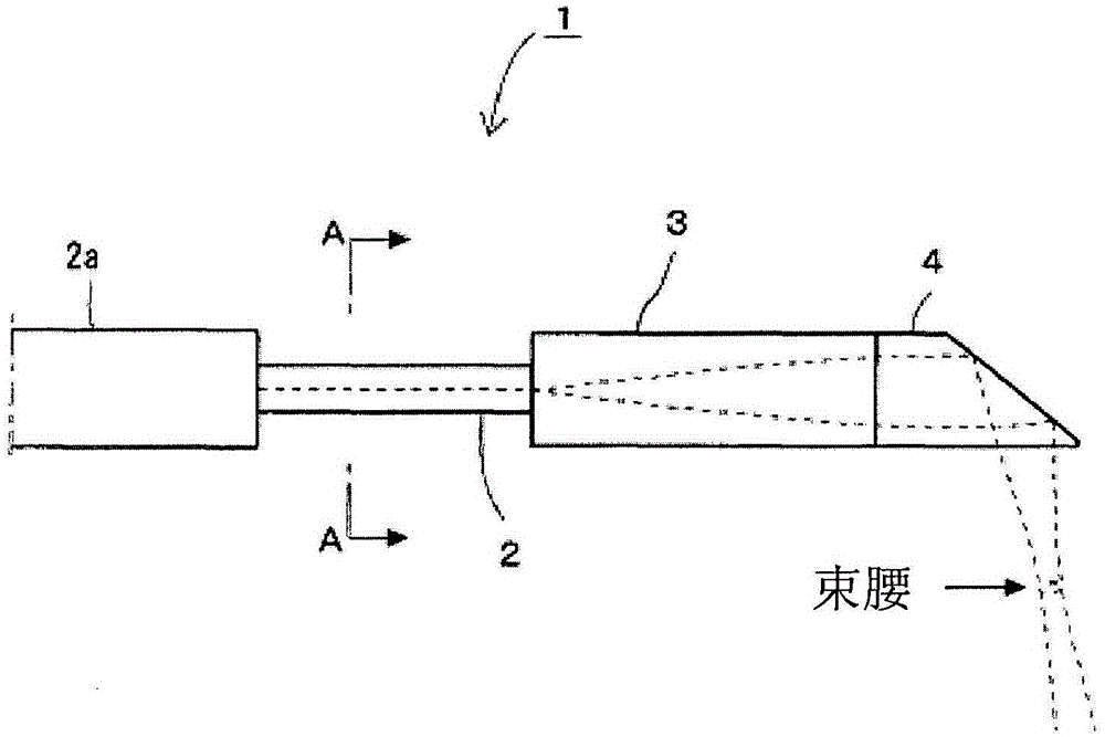
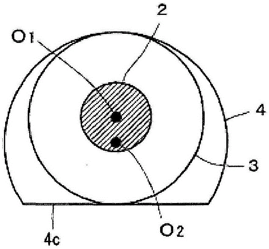
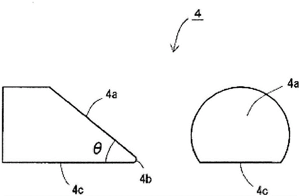
[0069] Figure 1~3 The side injection device 1 according to the embodiment of the present invention, figure 1 for the side view, figure 2 for figure 1 The A-A line sectional view, image 3 It is a side view (left side) and a front view (right side) of the prism 4.

[0070] The side emission device 1 is composed of an optical fiber 2 , a rod lens 3 and a prism 4 .

[0071] The optical fiber 2 is a single-mode optical fiber with an outer diameter of 125 μm, and the covering 2 a at the tip is removed, and a rod lens 3 is welded to the tip.

[0072] The rod lens 3 is a GRIN lens made of quartz-based glass with an outer diameter of 200 μm and a numerical aperture NA=1.53. The axes of the optical fiber 2 and the rod lens 3 are automatically aligned by the self-alignment effect during welding.

[0073] The prism 4 is quartz glass, and has a basic shape of a planar emission surface 4c parallel to the axis (the width of the emission surface is 200 μm) by cutting off a part of t...


PUM

PropertyMeasurementUnit
diameteraaaaaaaaaa

Abstract

Provided is a side emitting device such that the coupling efficiency at the part where a rod lens and a prism are fused is prevented from worsening, the outside diameter of the side emitting device can be made extremely thin, and the distance to a beam waist can be made long. The side emitting device has: an optical fiber (2); a rod lens (3) fused on one end to an end surface of the optical fiber; and a prism (4) fused to the other end of the rod lens. The prism forms a base shape in which part of the circumference of a cylinder is cut out so that a flat emission surface (4c) parallel to the axial line is formed. At the part where the rod lens and the prism are fused to each other, the outer diameter of the fusion end of the rod lens is equal to or less than the smallest diameter of the fusion end surface of the prism. The center (O1) of the fusion end surface of the rod lens and the center (O2) of the circular arc of the fusion end surface of the prism are offset from each other without the fusion end surface of the rod lens protruding from the fusion end surface of the prism.

Description

technical field [0001] The present invention relates to a side emitting device for emitting light propagating in an optical fiber to the side forming an angle with respect to the optical axis of the optical fiber, in particular to a side emitting device suitable for use as an optical probe for OCT (Optical Coherence Tomography) device. Background technique [0002] OCT is to insert the optical probe into the patient's blood vessels, intestines and other organs, emit low coherent light from the front end to the side, and use the light reflected from various parts inside the subject to obtain the precision inside the subject. The optical coherence tomography method of the tomographic image, its basic technology is disclosed in Japanese Patent Publication No. 6-35946 (Patent Document 1), and the specific structure of the optical probe is disclosed in WO2011 / 074051 International Publication Bulletin (Patent Document 2 ), Japanese Patent No. 4659137 (Patent Document 3) and the l...

Claims


Application Information

Patent Timeline
Patent Type & Authority Applications(China)
IPC IPC(8): G02B6/26A61B1/00G01N21/17G02B6/02
CPCG02B6/262A61B1/0615A61B1/07G02B6/34A61B5/0066A61B5/0084G02B5/04G02B6/0008
Inventor 丸山直文福田敏明
Owner TOYO SEIKAN GRP HLDG LTD
Why Eureka
Try Eureka