
A Control Method for Reducing Switching Tube Voltage Spikes and Circulating Current in Bidirectional Forward Converter

A forward converter, voltage spike technology, applied in the direction of converting DC power input to DC power output, control/regulation systems, instruments, etc., can solve the problems of high voltage spike, performance degradation, circuit volume and efficiency not conducive to improvement, etc. , to reduce voltage and current spikes, improve safety and reliability

Inactive Publication Date: 2017-12-26
NO 719 RES INST CHINA SHIPBUILDING IND
View PDF6 Cites 0 Cited by
  • Summary
  • Abstract
  • Description
  • Claims
  • Application Information

AI Technical Summary

Problems solved by technology

In the application process of the bidirectional forward converter, due to the existence of the leakage inductance, the switching tube will form a large voltage spike at the moment of turning off, especially in the process of transmitting power from the low voltage side to the high voltage side, there will be two In the series process of inductance (filter inductance and leakage inductance) with different currents, the voltage peak in this process is very high, and it is difficult to absorb or the absorption circuit loses a lot, which is not conducive to the safe and efficient operation of the switch tube, and the volume and efficiency of the entire circuit are also reduced. Not conducive to improving
[0005] The excessive voltage spike of the switching tube has severely limited the application of the bidirectional forward converter and greatly reduced its performance
Aiming at this problem, there is no very practical and effective solution

Method used


Image

  • A Control Method for Reducing Switching Tube Voltage Spikes and Circulating Current in Bidirectional Forward Converter
  • A Control Method for Reducing Switching Tube Voltage Spikes and Circulating Current in Bidirectional Forward Converter
  • A Control Method for Reducing Switching Tube Voltage Spikes and Circulating Current in Bidirectional Forward Converter

Examples


Embodiment Construction

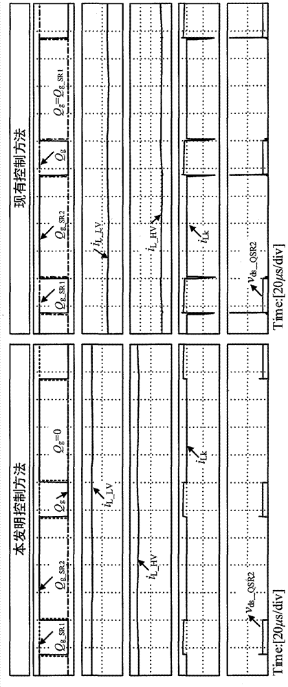
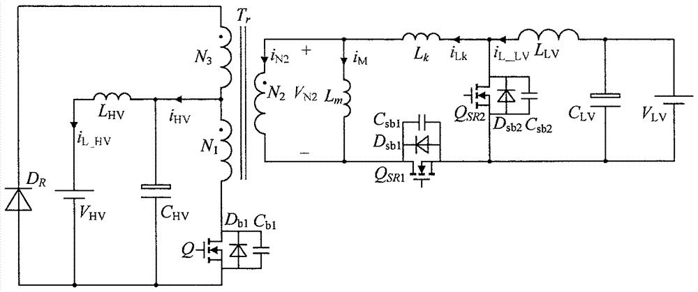
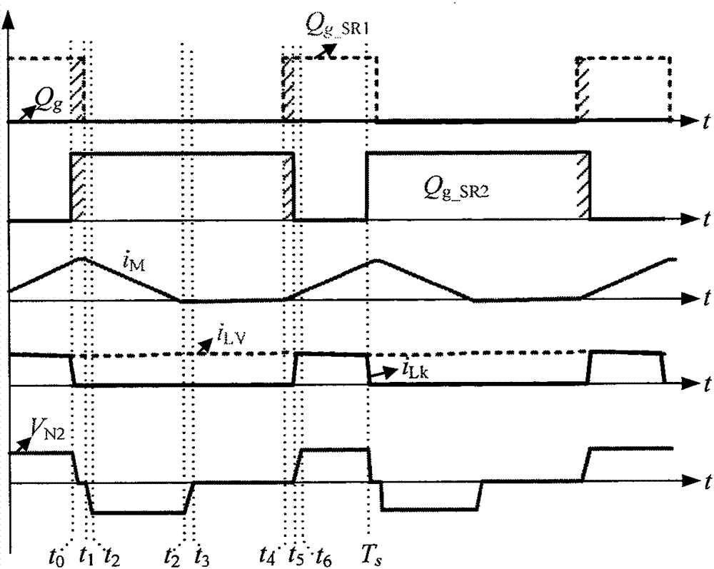
[0037] The following is attached with the manual Figure 1-12 A control method for reducing voltage spikes and circulating currents of switching tubes of bidirectional forward converters of the present invention is described in detail.

[0038] figure 1 Is the main circuit diagram of the bidirectional forward converter. Such as figure 1 As shown, the bidirectional forward converter includes a high side power supply V HV , High voltage side filter inductor L HV , Low-voltage side filter capacitor C HV , High frequency transformer T r , reset diode D R , high-voltage side switch tube Q, low-voltage side release switch tube Q SR1 , Low-voltage side energy storage switch tube Q SR2 , Low-voltage side filter inductor L LV , Low-voltage side filter capacitor C LV and low side supply V LV . Among them, N 1 , N 2 and N 3 Respectively T r The high voltage side winding, low voltage side winding and reset winding, L m and L k Respectively T r Magnetizing inductance and...


PUM


Abstract

The invention discloses a control method for effectively reducing the voltage peak and circulating current of a switching tube of a bidirectional forward converter, mainly aimed at the working condition that the bidirectional forward converter transmits power from the low-voltage side to the high-voltage side, and the low-voltage side switching tubes QSR1 and QSR2 are low Level complementary switching control, there is a high-level common conduction time, and the high-voltage side switch Q is always turned off; Qg, Qg_SR1 and Qg_SR2 correspond to the drive control signals of the switch Q, QSR1 and QSR2, and the high level corresponds to the switch. Turn on, the low level corresponds to the switch off, within a switching cycle, the high level time of Qg_SR1 is less than 1 / 2 switching cycle, the high level time of Qg_SR2 is greater than 1 / 2 switching cycle, Qg keeps low level . The invention is simple to implement, can effectively reduce the switch tube voltage, current peak and circulating current of the bidirectional forward converter, improve the safety, efficiency and power density of the converter, and increase the transmission power.

Description

technical field [0001] The invention belongs to the technical field of DC-DC electric energy conversion, and in particular relates to a control method for reducing voltage peaks and circulating currents of switch tubes of bidirectional forward converters. Background technique [0002] The bidirectional DC-DC converter is a dual-quadrant operation of the DC converter, which can realize bidirectional transmission of energy. It is functionally equivalent to two unidirectional DC converters and is a typical "one machine with two uses" device. The size, weight and cost of the system can be greatly reduced when bidirectional energy flow is required. Due to this advantage, bidirectional DC-DC converters have been widely used in aviation power supplies, new energy power generation systems, electric vehicles, uninterruptible power supplies, energy storage systems and other fields. [0003] According to whether it is electrically isolated, bidirectional DC-DC converters can be divide...

Claims


Application Information

Patent Timeline
Patent Type & Authority Patents(China)
IPC IPC(8): H02M3/335H02M1/32
Inventor 姚川吴浩伟李鹏李小谦张明邓磊李锐蔡凯欧阳晖姜波李可维周樑邢贺鹏金惠峰孙朝晖耿攀谢炜吴大立徐正喜陈涛魏华
Owner NO 719 RES INST CHINA SHIPBUILDING IND
Learn More