
Magnetron sputtering apparatus

A magnetron sputtering and equipment technology, applied in the field of magnetron sputtering technology, can solve the problems of low sputtering efficiency, uncontrollable deposition particles and deposition rate, etc., and achieve the effect of increasing the number of collisions

Inactive Publication Date: 2015-11-25
上海正相实业有限公司
View PDF2 Cites 5 Cited by
  • Summary
  • Abstract
  • Description
  • Claims
  • Application Information

AI Technical Summary

Problems solved by technology

[0005] The purpose of the present invention is to overcome the shortcomings and deficiencies in the above-mentioned prior art, and propose a magnetron sputtering device and a magnetron sputtering method, improve the flatness and uniformity of the film, and solve the problems of low sputtering efficiency and deposition Problems with uncontrollable particle and deposition rates

Method used


Image

  • Magnetron sputtering apparatus
  • Magnetron sputtering apparatus
  • Magnetron sputtering apparatus

Examples


Embodiment Construction

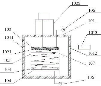
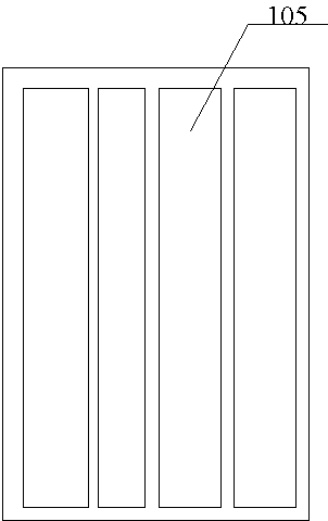
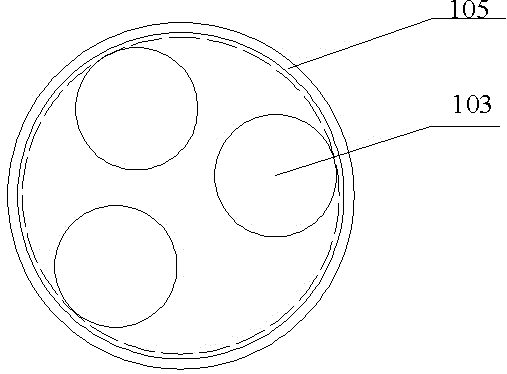
[0023] see figure 1 , the magnetron sputtering device of the present invention includes a magnetron sputtering chamber 101, which is a cylindrical or cuboid container that can form a closed space, and its left and right side walls are respectively provided with an air inlet 1011 and an air inlet 1012, and the air inlet The gas port 1012 is connected with a vacuum pump 1013; the sputtering target 103 and the target material 104 are located in the lower part of the magnetron sputtering chamber; the magnet 1041 is a permanent magnet located at the bottom of the sputtering target in the magnetron sputtering chamber, and the magnetic field strength is 10 -2 ~1T; the movable substrate table 102 is located in the upper part of the magnetron sputtering chamber and can move up and down, and a substrate 1021 is arranged on the opposite surface of it and the sputtering target 103; the protective cover 105 is located in the magnetron sputtering chamber and placed Between the target materi...


PUM


Abstract

The invention provides a magnetron sputtering apparatus. The magnetron sputtering apparatus comprises: a magnetron sputtering chamber, wherein the left and right sidewall of the magnetron sputtering chamber are respectively provided with an air inlet and an air exhausting opening; a sputtering target and a target material, which are positioned in the lower part of the magnetron sputtering chamber; a magnet, which is positioned at the bottom of the sputtering target in the magnetron sputtering chamber; a movable substrate bench, which is positioned in the upper part of the magnetron sputtering chamber and is provided with a substrate on a surface opposite to the sputtering target; a protective cover, which is positioned in the magnetron sputtering chamber and placed between the target material and the movable substrate bench; a high frequency power supply, which is located out of the magnetron sputtering chamber, wherein the positive and negative electrodes of the high frequency power supply are respectively connected with the substrate bench and the sputtering target; and an energized coil, which is vertically arranged between the substrate bench and the sputtering target and used for generating changing magnetic fields. The magnetron sputtering apparatus provided by the invention can increase the rate of collision between electrons and deposited particles, thereby achieving the purposes of controlling particle sizes and a deposition speed and realizing magnetron sputtering deposition of a nanometer film.

Description

technical field [0001] The invention relates to a magnetron sputtering technology, in particular to a magnetron sputtering device. Background technique [0002] The magnetron sputtering process is simple and efficient, low temperature, energy saving, and pollution-free, and is widely used in integrated circuits, liquid crystal displays, thin-film solar cells and other fields. [0003] At present, semiconductors and optoelectronic devices require more and more refined manufacturing processes, and thin-film technology on the order of several nanometers has become a key process in the manufacturing process. In the prior art, the growth of nano-scale thin films mainly relies on some more sophisticated deposition techniques, such as molecular beam epitaxy, metal-organic chemical vapor deposition, plasma-enhanced chemical vapor deposition and other system equipment. However, from the perspective of economy and environmental protection , the above-mentioned equipment and process a...

Claims


Application Information

Patent Timeline
Patent Type & Authority Applications(China)
IPC IPC(8): C23C14/35
Inventor 宋太伟高伟波
Owner 上海正相实业有限公司
Learn More