Laser machining device and system for producing optical display device

A laser processing and optical display technology, applied in optics, identification devices, nonlinear optics, etc., can solve problems affecting product processing accuracy, production line pollution, and difficulty in complete removal, so as to prevent production line pollution, expand effective area, and inhibit adhesion Effect

Inactive Publication Date: 2015-11-25
SUMITOMO CHEM CO LTD
View PDF10 Cites 0 Cited by
  • Summary
  • Abstract
  • Description
  • Claims
  • Application Information

AI Technical Summary

Problems solved by technology

[0009] In the former structure, although the adhesion of dust to the product can be suppressed, it is difficult to completely remove it. In the case of strict product specifications, the adhesion of foreign matter to the surface of the product becomes a problem.
In addition, there may be a decrease in yield due to contamination of the production line caused by tiny foreign matter adhering to the product surface
[0010] In the above-mentioned latter structure, although the adhesion of smoke and dust to the optical film is suppressed by tilting the laser irradiation direction, the cut surface of the film tends to become tapered due to the inclination of the optical axis, which may affect the processing accuracy of the product.
In addition, it may become a defective product in terms of product specifications

Method used


Image

  • Laser machining device and system for producing optical display device
  • Laser machining device and system for producing optical display device
  • Laser machining device and system for producing optical display device

Examples


Embodiment Construction

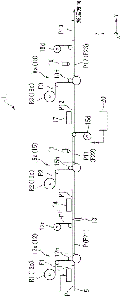
[0055] Hereinafter, embodiments of the present invention will be described with reference to the drawings. In this embodiment, as a production system of an optical display device, a film bonding system constituting a part thereof will be described. In each drawing, an XYZ rectangular coordinate system is set. The X direction represents the width direction of the optical display element (liquid crystal panel). The Y direction represents the conveyance direction of the optical display element. The Z direction represents a direction perpendicular to the X direction and the Y direction.

[0056] figure 1 The schematic structure of the film bonding system (production system of an optical display device) 1 of this embodiment is shown. The film bonding system 1 bonds a sheet-shaped optical member such as a polarizing film, a retardation film, or a brightness enhancement film to a panel-shaped optical display element such as a liquid crystal panel or an organic EL panel. The film...


PUM


Abstract

The present invention provides a laser machining device, which is capable of effectively limiting the adhesion of fumes on the product surface without affecting product machining precision, and a system for producing optical display devices. The laser machining device is provided with a suction unit (30) that has a suction opening (37) along the entire length of the cutting line (SX) of an optical member sheet (FX) in an optical display component (PX) near the cutting line.

Description

technical field [0001] The invention relates to a laser processing device and a production system of an optical display device. [0002] This application claims priority based on Japanese Patent Application No. 2013-80846 for which it applied on April 8, 2013, and Japanese Patent Application No. 2013-104400 for which it applied on May 16, 2013, and uses the content here. Background technique [0003] In Patent Document 1, the following technology is disclosed: by using a suction device with a suction port arranged near the laser irradiation part to suck and remove the decomposition products (dust) generated from the laser irradiation part during the laser processing of the product, thereby reducing the Adhesion of smoke and dust to the surface of the product. [0004] Patent Document 2 discloses a technique in which, in the method of cutting an optical film with a diaphragm into a predetermined length and laminating it to a product panel, the laser axis is positioned forwar...

Claims


Application Information

Patent Timeline
Patent Type & Authority Applications(China)
IPC IPC(8): B23K26/142B23K26/38B23K26/40G02F1/13G09F9/00
CPCB23K26/38B23K26/142B23K26/361B23K26/40B23K2203/172G02F1/1303B23K2103/172
Inventor 土冈达也岸崎和范
Owner SUMITOMO CHEM CO LTD
Why Eureka
Try Eureka