
An ultra-thin high-voltage resistant metallized film evaporation equipment

A technology of metallized thin film and high pressure resistance, which is applied in vacuum evaporation coating, metal material coating process, sputtering coating, etc., and can solve the problem of insufficient uniformity of coating thickness of metallized thin film products, and uniform structure and texture of metal wires Problems such as linearity error and wire feed rate deviation of wire feed wheel can be solved to improve the thickness control level, reduce the overall thickness requirement, and improve the pressure resistance and ultra-thin performance.

Inactive Publication Date: 2017-07-14
ANHUI NINGGUO HAIWEI ELECTRONICS
View PDF5 Cites 0 Cited by
  • Summary
  • Abstract
  • Description
  • Claims
  • Application Information

AI Technical Summary

Problems solved by technology

[0006] The continuous vapor deposition equipment in the prior art usually has a relatively large width, and can vapor deposit multiple metallized films at the same time. After the evaporation is completed, the entire metallized film is cut into multiple strips by a cutting device. For a metal evaporation furnace with a large width, it is usually necessary to arrange several evaporation boats in parallel, and each evaporation boat is correspondingly equipped with a wire feed wheel. Because there are certain errors in the shape structure and texture uniformity of the metal wire, and the wire feed wheel There is also a deviation in the wire feeding rate, resulting in a difference in the rate of metal vapor generated in each evaporation boat, resulting in insufficient uniformity of the coating thickness of the metallized film product, which needs to be further improved

Method used


Image

  • An ultra-thin high-voltage resistant metallized film evaporation equipment
  • An ultra-thin high-voltage resistant metallized film evaporation equipment
  • An ultra-thin high-voltage resistant metallized film evaporation equipment

Examples


Embodiment Construction

[0026] The content of the present invention will be described below in conjunction with specific embodiments.

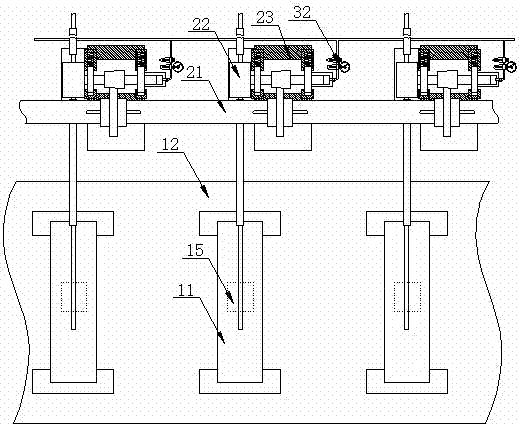
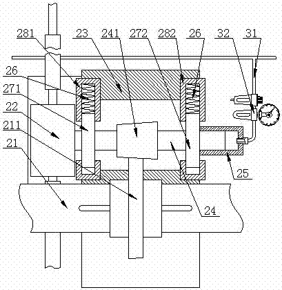
[0027] Such as Figure 1 to Figure 4 As shown, it is a schematic structural diagram of an ultra-thin high-voltage metallized film evaporation equipment according to the present invention. An ultra-thin high-voltage resistant metallized film evaporation device described in the present invention comprises:

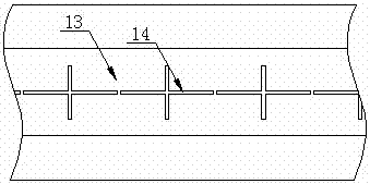
[0028] An evaporation mechanism for heating and evaporating metals. The evaporation mechanism includes several evaporation boats 11; the evaporation mechanism also includes an evaporation furnace 12 and an evaporation spray plate 13 arranged above the evaporation furnace 12. And located below the evaporation spray plate 13, the evaporation spray plate 13 is provided with a hollow evaporation spray tank 14, and the bottom of the evaporation furnace 12 is provided with several exhaust ports 15, several exhaust ports 15 and several evaporation boats 11 One to one co...


PUM


Abstract

The invention discloses an ultra-thin high-voltage resistant metallized film evaporation equipment, which includes an evaporation mechanism for heating and evaporating metals, and the evaporation mechanism includes several evaporation boats; and is used for transporting evaporation materials into the evaporation mechanism A wire feeding mechanism for metal wire, the wire feeding mechanism includes a main drive shaft and several transmission assemblies driven by the main drive shaft, each of the transmission assemblies includes a wire feed wheel; and is used to control the feeding The control mechanism of the wire feeding rate of the wire mechanism, each of the control mechanisms includes a signal collector for detecting the evaporation rate of the evaporation boat, a signal for processing the detection signal collected by the signal collector and outputting a control signal A processor, and a signal actuator for adjusting the wire feeding plastic of the wire feeding wheel by receiving the control signal output by the signal processor and adjusting the transmission ratio of the transmission assembly. The invention can improve the vapor deposition thickness uniformity of the metallized thin film metal coating.

Description

technical field [0001] The invention relates to an ultra-thin high-voltage resistant metallized film evaporation equipment, which belongs to the technical field of metallized film manufacturing equipment. Background technique [0002] The metallized film used to manufacture film capacitors consists of an insulating dielectric film and an evaporated metal layer, and a metal thin film is evaporated on the surface of the insulating dielectric film through a vacuum evaporation process. [0003] Among them, the insulating dielectric film is mainly composed of polypropylene and polyester film. Biaxially stretched polypropylene film in polypropylene film is widely used. Biaxially stretched polypropylene film has high mechanical and electrical properties. Biaxially stretched Capacitors manufactured by vacuum evaporation of polypropylene film have significant advantages such as low heat shrinkage, stable performance, high temperature resistance, high pressure resistance, and breakdow...

Claims


Application Information

Patent Timeline
Patent Type & Authority Patents(China)
IPC IPC(8): C23C14/24
Inventor 宋仁祥
Owner ANHUI NINGGUO HAIWEI ELECTRONICS
Learn More