Rotor system for hybrid kinetic energy power generation device

A power generation device and kinetic energy technology, applied in the direction of generating mechanical power with physical force, mechanisms for generating mechanical power, machines/engines, etc., can solve the problems of lack of scientific operability, inability to meet high torque, and application range stop, etc., to achieve The effect of large torque, large moment of inertia, and small starting torque

Active Publication Date: 2015-12-02
JIANGSU ZHONGYUN WIND POWER SCIENCE & TECHNOLOGY CO LTD
View PDF10 Cites 1 Cited by
  • Summary
  • Abstract
  • Description
  • Claims
  • Application Information

AI Technical Summary

Problems solved by technology

[0003] Chinese invention patent CN201020001199.7 discloses a lever-type animal power generating set, Chinese invention patent CN201120399127.7 discloses a hybrid kinetic energy power generation system for animal power generation, and Chinese invention patent CN201210015343.6 discloses an intelligent animal power generation Hybrid kinetic energy power generation system, Chinese invention patent CN201310747539.9 discloses a three-dimensional multi-storey animal power generation station. The above four patents all disclose the basic principle and structure of the kinetic energy power generation system using animal power, but the above-mentioned disclosed power generation system The structure is simple, and its application range always stays in the field of small power (within 5KW) supplementary emergency power supply technology. Its target customers are areas without electricity and households, but the application effect is not good. The generation of kinetic energy in the above kinetic energy generation system is limited to The conversion lacks scientific operability, the input of kinetic energy is large, and the output of electric energy is small. The traditional animal husbandry grinding method cannot exert its due special effects, and the rotor part adopts a common speed-up structure with large teeth and small teeth, which cannot meet high torque. , low speed, high gear ratio special speed-up technology, so it is urgent to design a new rotor system

Method used


Image

  • Rotor system for hybrid kinetic energy power generation device
  • Rotor system for hybrid kinetic energy power generation device
  • Rotor system for hybrid kinetic energy power generation device

Examples


Embodiment Construction

[0024] The specific implementation manner of the present invention will be described below in conjunction with the accompanying drawings.

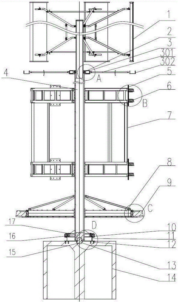
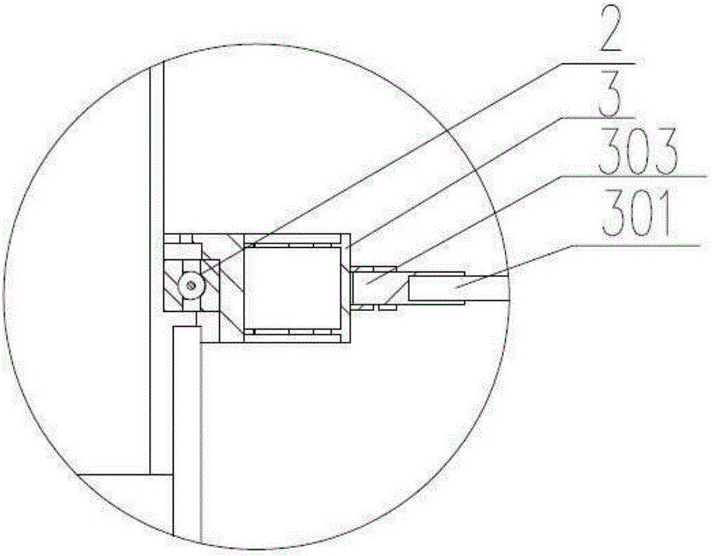
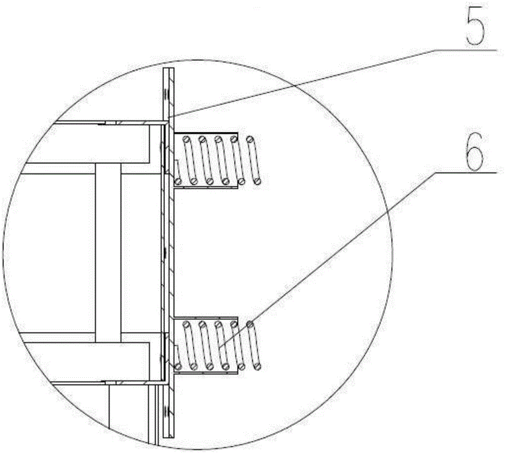
[0025] like Figure 1 to Figure 5 As shown, a rotor system for a hybrid kinetic energy generating device includes a hollow main transmission shaft 4, which is located at the bottom of the main transmission shaft 4, and is connected to a shaft sleeve 16 inside the main transmission shaft 4, and a hemispherical gyro rotor 13 and shaft The sleeve 16 is connected; along the outer circumference of the main transmission shaft 4, the adjustment wheel 3, the squirrel-cage frame 7, the gear plate 8 and the slewing bearing 10 are respectively installed from top to bottom, and the squirrel-cage frame 7 is passed through the frame by the discs arranged up and down. A multi-layer rotor structure is formed in series; a rolling bearing 2 for cooperating with the outer periphery of the main transmission shaft 4 is arranged inside the adjustment wheel 3; a...


PUM


Abstract

The invention relates to a rotor system for a hybrid kinetic energy power generation device. The rotor system comprises a hollow main transmission shaft. A shaft sleeve is connected to the position, at the bottom of the main transmission shaft, inside the main transmission shaft. A gyrorotor is connected with the shaft sleeve. The main transmission shaft is sleeved with an adjustment wheel, a squirrel cage frame, a gear disk and a slewing bearing in sequence from top to bottom. The squirrel cage frame is of a multi-layer rotor structure formed by connecting upper and lower disks in series through a frame body. A rolling bearing used for being matched with the periphery of the main transmission shaft is arranged in the adjustment wheel. A bevel gear is arranged on the outer ring of the gear disk in a matched mode. The inner ring of the slewing bearing is connected with a connecting flange of the main transmission shaft, and the connecting flange is integrally connected to the periphery of the main transmission shaft. The rotor system can meet the requirement for a high-power, low-torque, multi-tooth and high-modulus rotator, effectively achieve conversion from low-speed biological steeping kinetic energy to high-speed kinetic energy needed by a generator and supply high-quality and low-price power to ten millions of users.

Description

technical field [0001] The invention relates to rotor power equipment, in particular to a rotor system for a hybrid kinetic energy generating device. Background technique [0002] With the progress and development of science and technology, rotating machinery has gradually developed from the previous low speed and low power to high speed, high power, high precision and automation. Large-scale rotating machinery is one of the key equipment in national infrastructure and basic industries. It also puts forward higher requirements for the power characteristics, reliability and stability of rotating machinery. These practical needs promote the development of rotor dynamics. In order to prevent environmental degradation and further depletion of natural resources, renewable green electric energy is increasingly recognized by the public, and the use of biomass energy makes future power generation technology must comply with the principle of sustainable development. [0003] Chinese...

Claims


Application Information

Patent Timeline
Patent Type & Authority Applications(China)
IPC IPC(8): F03G5/04
Inventor 李勇强谢玉琪姚伯龙吴飞汪旭
Owner JIANGSU ZHONGYUN WIND POWER SCIENCE & TECHNOLOGY CO LTD
Why Eureka
Try Eureka