Raman sensing temperature measurement system in double-end injection annular structure, and Raman sensing temperature measurement method

A technology of Raman sensing temperature measurement and ring structure, applied in the field of temperature measurement system, can solve the problems of not being able to fully and truly reflect the temperature information along the optical fiber, increasing temperature measurement error, slow measurement error, etc.

Inactive Publication Date: 2015-12-02
MINNAN NORMAL UNIV
View PDF6 Cites 11 Cited by
  • Summary
  • Abstract
  • Description
  • Claims
  • Application Information

AI Technical Summary

Problems solved by technology

However, due to the wavelength-dependent loss of Stokes light and anti-Stokes light in the optical fiber, the temperature measurement curve obtained by the sensing system cannot completely reflect the temperature information along the optical fiber.
In practical applications, environmental changes will also change the wavelength-dependent loss and local loss of the sensing fiber at any time, resulting in slow and imperceptible measurement errors in the temperature measurement curve demodulated by

Method used


Image

  • Raman sensing temperature measurement system in double-end injection annular structure, and Raman sensing temperature measurement method
  • Raman sensing temperature measurement system in double-end injection annular structure, and Raman sensing temperature measurement method
  • Raman sensing temperature measurement system in double-end injection annular structure, and Raman sensing temperature measurement method

Examples


Embodiment Construction

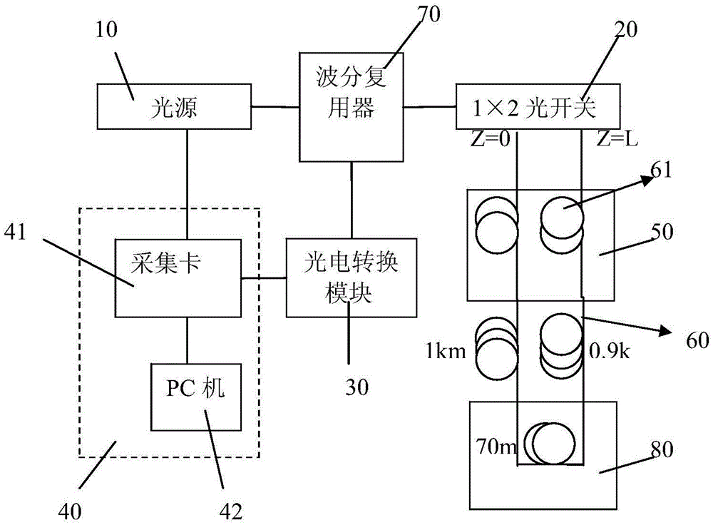
[0061] Please check figure 1 , in order to eliminate the influence of the optical fiber loss factor described in the background technology on temperature measurement, the present invention adopts a double-end injection ring structure to build a double-end injection ring structure Raman sensing temperature measurement system, the system includes a light source, a wavelength division multiplexer The light source is connected with the optical signal of the wavelength division multiplexer, the optical signal of the photoelectric conversion module is connected with the optical signal of the wavelength division multiplexer and the electrical signal of the data acquisition and processing module; It includes a 1x2 optical switch, the first and last ends of the sensing fiber are respectively connected to the 1x2 optical switch and the sensor optical fiber is arranged in a ring structure, the wavelength division multiplexer is connected to the 1x2 optical switch, and the 1x2 optical swit...


PUM


Abstract

The invention discloses a Raman sensing temperature measurement system in a double-end injection annular structure, and a Raman sensing temperature measurement method. The system comprises a light source, a wavelength division multiplexer, a photovoltaic conversion module, a sensing optical fiber, a signal collection and processing module, and a 1x2 optical switch. The head and tail ends of the sensing optical fiber are respectively connected with the 1x2 optical switch, and the sensing optical fiber is arranged in an annular structure. The 1x2 optical switch is connected to a head end optical circuit or a tail end optical circuit of the sensing optical fiber in a timing manner. The method comprises the steps: enabling the light of the light source to be injected to the head and tail ends of the sensing optical fiber in a timing manner, and correspondingly, obtaining anti-Stokes optical signals from the head and tail ends; enabling the obtained head-end and tail-end signals to be multiplied with each other, and then carrying out geometric averaging, thereby obtaining a result that optical fiber loss in an optical fiber temperature curve is not related with the position, and eliminating related loss of static wavelength and local loss. The method also achieves the normalization and self-collection of signals at an optical fiber ring through temperature control, thereby eliminating impact caused by photovoltaic conversion gain change and dynamic change of optical loss, and improving the temperature measurement precision.

Description

technical field [0001] The invention relates to a temperature measurement system and method, in particular to a Raman sensing temperature measurement system and method with double-end injection ring structure. Background technique [0002] Distributed Raman fiber optic sensors have many advantages such as long-distance distributed measurement, anti-electromagnetic interference, small size and light weight, etc., in urban gas pipelines, power transmission / communication cables, reservoir dams, bridges, tunnels, highways, etc., which require real-time temperature It has a wide range of applications in the field of monitoring. The traditional Raman optical fiber sensing scheme uses a single-ended injection method to simultaneously detect Stokes light and anti-Stokes signals in spontaneous Raman scattering, and use the ratio of the two for temperature demodulation. [0003] Among them, the anti-Stokes optical power is: [0004] P AS ...

Claims


Application Information

Patent Timeline
IPC IPC(8): G01K11/32G01K1/00G01K11/324
Inventor 陈福昌余超群张华林周锦荣
Owner MINNAN NORMAL UNIV
Why Eureka
Try Eureka