Active optical cable connector assembly

A technology for optical cable connectors and electrical connectors, which is applied in the field of active optical cable connector components, and can solve complex and cumbersome installation and debugging of optical cable connectors and optical cables, weak anti-vibration and shock resistance of optical modules, and lower transmission performance indicators of optical modules and other problems, to achieve the effect of simple and convenient installation and debugging, light weight and strong bending resistance

Active Publication Date: 2015-12-09
8TH RES INST OF CETC
View PDF6 Cites 4 Cited by
  • Summary
  • Abstract
  • Description
  • Claims
  • Application Information

AI Technical Summary

Problems solved by technology

[0005] 1. The gold finger electrical pin interface is a plug-in type. In the vibration and shock environment, the plug-in structure is prone to hidden dangers of poor contact. Therefore, when the gold finger electrical pin interface is used, the optical module can be used in a high-reliability application environment. The ability to resist vibration and shock is relatively weak, and the reliability cannot be guaranteed
[0006] 2. When the optical module is installed on the system circuit board, the system board needs to provide a larger space for the optical module to realize signal conversion and transmission. At the same time, because the optical fiber quartz glass material at the optical port of the optical module is easy to break, it is not suitable Excessive bending, so it has a minimum bending radius and needs to be coiled, which also occupies a large space, which is a large burden for manned spaceflight system engineering
[0007] 3. The interface between the optical fiber and the optical module is prone to fiber breakage and increased loss due to severe vibration and shock, thereby greatly reducing the transmission performance index of the optical module
[0008] 4. The separate structure makes the installation and debugging of optical modules, optical cable connectors and optical cables complicated and cumbersome

Method used


Image

  • Active optical cable connector assembly
  • Active optical cable connector assembly
  • Active optical cable connector assembly

Examples


Embodiment Construction

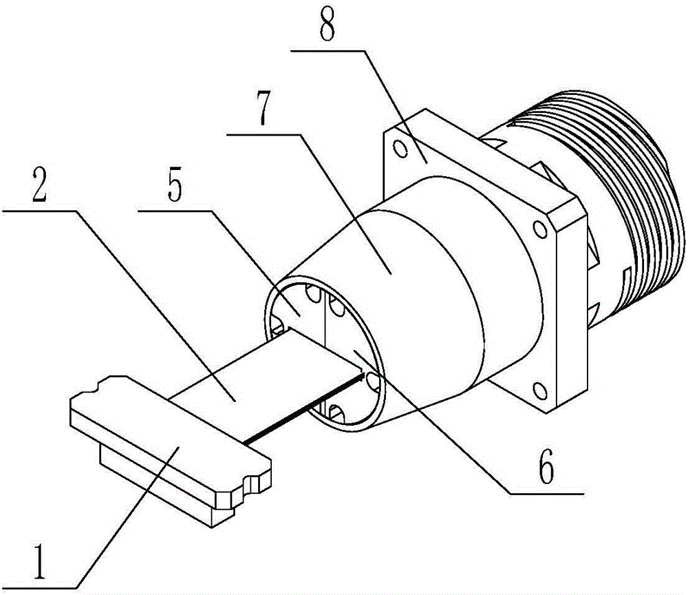
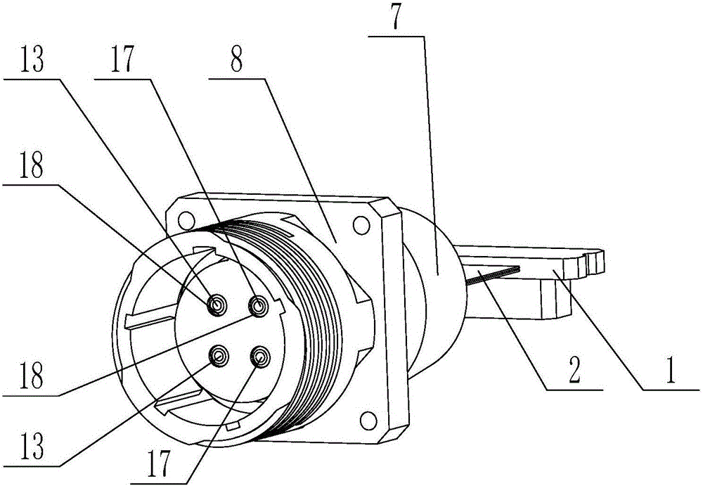
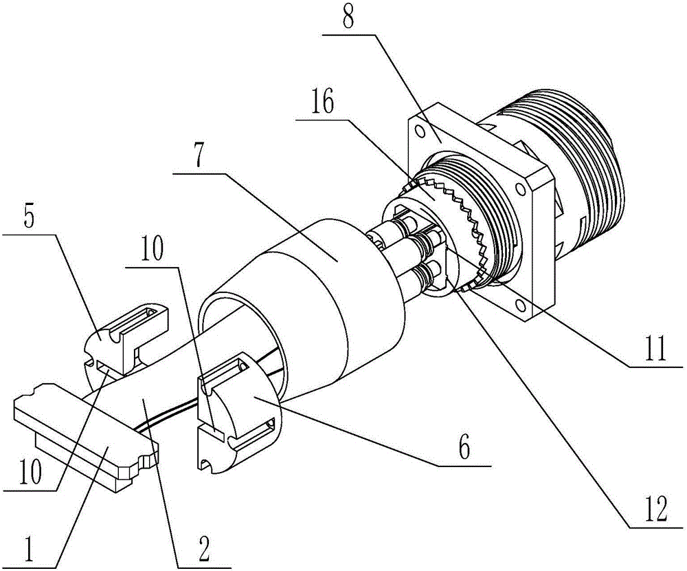
[0026] The active optical cable connector assembly of the present invention will be further described below in conjunction with the accompanying drawings and specific embodiments:

[0027] like figure 1 , figure 2 , image 3 , Figure 4 and Figure 5 As shown, the active optical cable connector assembly of the present invention includes a high-speed electrical connector 1, a flexible circuit board 2, an upper layer optical module 3, a lower layer optical module 4, a left half tail ring 5, a right half tail ring 6, and a boot 7 , the connector socket shell 8 and the plug 9 . Both the upper-layer optical module 3 and the lower-layer optical module 4 are electrically connected to the high-speed electrical connector 1 through a flexible circuit board 2 . The left half tail retaining ring 5 and the right half tail retaining ring 6 are combined and located in the boot 7, the left half tail retaining ring 5 and the right half tail retaining ring 6 are provided with a card slot ...


PUM


Abstract

Provided is an active optical cable connector assembly. The active optical cable connector assembly comprises a tail sleeve, a connector socket shell, a plug, a left half tail back-up ring and a right half tail back-up ring positioned in the tail sleeve after merging, and an upper layer optical module and a lower layer optical module electrically connected with a high-speed electric connector via flexible printed circuit boards, the left half tail back-up ring and the right half tail back-up ring are both provided with slots capable of clamping the flexible printed circuit boards, the connector socket shell is fixedly provided with a seat core provided with two optical module upper slots and two optical module lower slots in a pasted manner, the tail sleeve is connected with the connector shell, the upper layer optical module and the lower layer optical module are both positioned in the connector socket shell, and the connector socket shell and the plug are connected by employing a four-channel LC plug-pull type structure. The active optical cable connector assembly is advantageous in that the integration is realized, the size is small, the weight is low, anti-electromagnetic interference is provided, the reliability is high, the installation and the debugging are simple and convenient, the problems of fiber coiling of conventional pigtail optical modules and easy break of the optical fibers can be thoroughly solved, the spatial size of a manned space system can be greatly reduced, and the active optical cable connector assembly is very applicable to data transmission application in the manned space systems.

Description

Technical field: [0001] The invention relates to an active optical cable connector, in particular to an integrated, small size, light weight, anti-electromagnetic interference, high reliability, simple and convenient installation and debugging, which can completely solve the problem of traditional pigtail type optical module disk fiber and The problem of easy breakage of optical fibers can greatly save the space volume of manned spaceflight systems, and is very suitable for active optical cable connector components for data transmission applications in manned spaceflight systems. Background technique: [0002] At present, the existing optical communication systems at home and abroad are usually composed of optical modules at the two ends of the transceiver, optical cable connectors and transmission optical cables. The optical module, optical cable connector and transmission optical cable usually adopt a separate split structure, that is, the optical cable connector is usuall...

Claims


Application Information

Patent Timeline
IPC IPC(8): G02B6/36G02B6/44
CPCG02B6/36G02B6/3608G02B6/4439
Inventor 司淑平李锦华张玉琳高泽仁周雷谢飞曹明慧
Owner 8TH RES INST OF CETC
Why Eureka
Try Eureka