Flexible device and its preparation method

A technology of flexible devices and positive active materials, applied in the field of flexible devices, can solve the problems of easy fatigue, decreased bonding strength, and great difficulty, and achieve the effect of increasing the contact area, increasing the bonding strength, and simple preparation process

Active Publication Date: 2018-07-03
GUANGDONG ZHUGUANG NEW ENERGY TECH
View PDF7 Cites 0 Cited by
  • Summary
  • Abstract
  • Description
  • Claims
  • Application Information

AI Technical Summary

Problems solved by technology

However, when the flexible battery pack of this design is bent, due to the strong rigidity of the top layer and the bottom layer, the bending degree and fatigue strength of the flexible battery pack are greatly limited due to the influence of stress, which affects the performance of the flexible battery pack. After a certain bending angle and bending times, the bonding strength of the adhesive will decrease, resulting in poor reliability, and fatigue will easily occur in the non-bonding area close to the adhesive due to the inconsistent force, which is harmful to flexibility. The safety performance of the battery pack is at risk
Moreover, this method needs to control the bonding strength of the adhesive and the uniformity of the amount used in each area, and it is very difficult to mass produce

Method used


Image

  • Flexible device and its preparation method

Examples


Embodiment 1

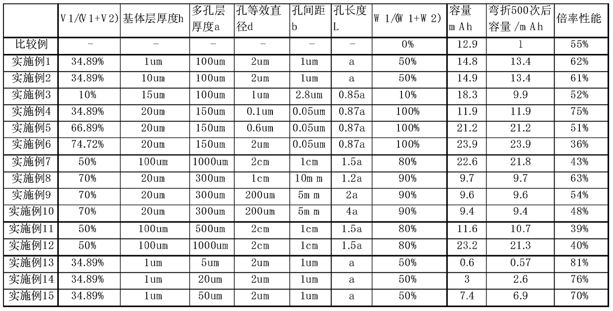
[0037] Preparation of porous current collector: choose an aluminum foil with a thickness of 1 μm as the base layer; select an aluminum foil with a thickness of 100 μm, and then use laser drilling to punch holes in the aluminum foil to obtain a circular hole shape and a hole diameter of 2 μm. The hole spacing (the distance between the closest edges of the two holes) is 1 μm, and the hole depth is 100 μm, so as to obtain the porous structure layer of the porous current collector; the above porous structure layer and the collective layer are cut, and then the conductive glue is used The porous structure layer is bonded on the substrate layer to obtain a porous current collector for use;

[0038] Positive electrode sheet preparation: Sulfur-porous carbon is used as the positive electrode active material (the loading capacity of sulfur is 70%), PVDF is used as the binder, Supper-P is used as the conductive agent (the mass ratio of the three is 94:3:3), and NMP is Solvent configurat...

Embodiment 2

[0041] The difference from Example 1 is that it includes the following steps:

[0042] Preparation of porous current collector: choose an aluminum foil with a thickness of 10 μm as the base layer.

[0043] The rest are the same as in Embodiment 1 and will not be repeated here.

Embodiment 3

[0045] The difference from Example 1 is that it includes the following steps:

[0046] Preparation of porous current collector: choose an aluminum foil with a thickness of 15 μm as the base layer; select an aluminum foil with a thickness of 100 μm, and then use laser drilling to punch holes in the aluminum foil to obtain a circular hole shape and a hole diameter of 1 μm. The hole spacing (the distance between the closest edges of the two holes) is 2.8 μm, and the hole depth is 100 μm, so as to obtain the porous structure layer of the porous current collector; the above porous structure layer and the collective layer are cut, and then the conductive glue is used The slurry porous structure layer is bonded to the substrate layer to obtain a porous current collector for use;

[0047] Positive electrode sheet preparation: Sulfur-porous carbon is used as the positive electrode active material (the loading capacity of sulfur is 70%), PVDF is used as the binder, Supper-P is used as t...


PUM

PropertyMeasurementUnit
thicknessaaaaaaaaaa
thicknessaaaaaaaaaa
thicknessaaaaaaaaaa

Abstract

The invention belongs to the technical field of flexible devices, and particularly relates to a flexible device: comprising a positive electrode sheet, a negative electrode sheet and a separator, the positive electrode sheet is composed of a negative electrode active material and a negative electrode current collector; the positive electrode current collector is composed of a porous structure layer and a matrix layer The porous structure layer includes a porous structure area and a non-porous area, the volumes of the porous structure area and the non-porous area are V1 and V2 respectively, and V1 / (V1+V2)≥10%; the positive active material is distributed in the pores of the porous structure layer In the structure or the surface of the non-porous area of ​​the porous structure layer, the quality of the active material distributed in the pore structure of the porous structure layer is W1, and the quality of the active material distributed on the surface of the non-porous area of ​​the porous structure layer is W2, and W1 / (W1+W2)≥10%. The present invention adopts a porous current collector, which can increase the adhesive force between the current collector and the active material, and ensure that the interface of the flexible device is closely bonded during the bending process; therefore, the prepared flexible device has more excellent flexibility and electrochemical performance.

Description

technical field [0001] The invention belongs to the technical field of flexible devices, in particular to a flexible device and a preparation method thereof. Background technique [0002] In 1991, Sony Corporation of Japan creatively adopted carbon materials as the anode material of lithium-ion batteries, which brought revolutionary changes in the field of lithium-ion batteries; And a lot of use on other portable electrical appliances. Lithium-ion batteries have many advantages, such as high voltage, small size, light weight, high specific capacity, no memory effect, no pollution, small self-discharge, long cycle life, etc. It is an ideal power source for mobile appliances and electric vehicles in the 21st century. Power supply and electric storage for storage power station. [0003] However, with the development of electronic devices towards personalization, a large number of creative electronic products have emerged rapidly: wearable devices such as smart watches, smart ...

Claims


Application Information

Patent Timeline
Patent Type & Authority Patents(China)
IPC IPC(8): H01M4/80H01M10/058H01M10/0525
CPCH01M4/80H01M10/0525H01M10/058Y02E60/10Y02P70/50
Inventor 杨玉洁
Owner GUANGDONG ZHUGUANG NEW ENERGY TECH
Why Eureka
Try Eureka