Method for generating ultra-wideband multi-band frequency microwave signal

A microwave signal and generation method technology, applied in electromagnetic wave transmission systems, electromagnetic transmitters, electrical components, etc., can solve the problems of few frequency components, narrow and not many multi-band microwave signal spectrum bandwidths, etc., to achieve easy control, good Spectral characteristics, easy tuning effect

Active Publication Date: 2015-12-09
南京云巅电子科技有限公司
5 Cites 6 Cited by

AI-Extracted Technical Summary

Problems solved by technology

So far, there are not many technologies for generating multi-band microwave signals using light, and th...

Abstract

The invention discloses a method for generating an ultra-wideband multi-band frequency microwave signal. The method comprises the following steps that a laser diode (LD) is taken as an input light source, an optical signal of the laser diode is averagely divided into two parts by an optical power splitter, and the two parts are respectively injected into a first frequency modulator (FM1) and a second frequency modulator (FM2) to carry out frequency modulation; the first frequency modulator (FM1) and the second frequency modulator (FM2) are respectively driven by a first radio-frequency signal (RF1) with the frequency of f1 and a second radio-frequency signal (RF2) with the frequency of f2, so that a first optical frequency comb (OFC1) with the frequency space of f1 and a second optical frequency comb (OFC2) with the frequency space of f2 are generated; and the two optical frequency combs are injected together through a coupler, and after frequency mixing, the ultra-wideband multi-band frequency microwave signal with the frequency space of deltaf=absolute value of f1-f2 is generated through beat frequencies of the optical frequency combs. The ultra-wideband multi-band frequency microwave signal which is generated based on the beat frequencies of the optical frequency combs has advantages on the spectral bandwidth and the frequency component, and the frequency space is tunable.

Application Domain

Electromagnetic transmitters

Technology Topic

Optical powerPhysics +15

Image

  • Method for generating ultra-wideband multi-band frequency microwave signal
  • Method for generating ultra-wideband multi-band frequency microwave signal
  • Method for generating ultra-wideband multi-band frequency microwave signal

Examples

  • Experimental program(2)

Example Embodiment

[0030] Example one
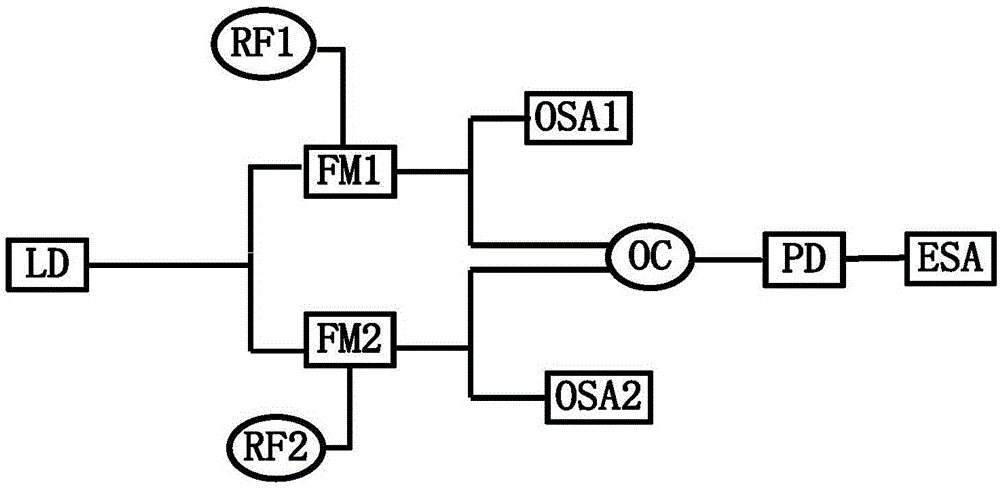
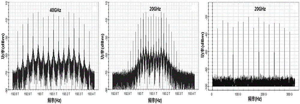
[0031] 1. After the light source is modulated by FM1 and FM2, OFC1 and OFC2 with frequency spacing of 40GHz and 20GHz are generated. After beating the frequency, a multi-band microwave signal with a frequency spacing of 20GHz, a spectral bandwidth of 300GHz, and spectral line purity is obtained ( See attached figure 2 ).
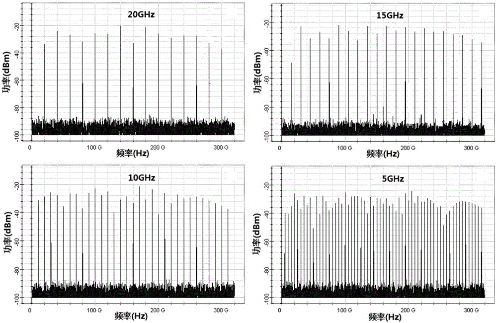
[0032] 2. When setting the frequency of RF1 and RF2 to f 1 =40GHz, f 2 =20GHz; f 1 =30GHz, f 2 =15GHz; f 1 =20GHz, f 2 =10GHz; f 1 =10GHz, f 2 = 5GHz, the corresponding RF1 and RF2 frequency difference Δf is 20GHz, 15GHz, 10GHz and 5GHz in order, and the multi-band microwave signals with frequency intervals of 20GHz, 15GHz, 10GHz and 5GHz are obtained (see attached image 3 ).

Example Embodiment

[0033] Example two
[0034] 3. Other parameters remain unchanged. Set the frequency offsets of FM1 and FM2 to 400GHz and 200GHz; 360GHz and 180GHz; 120GHz and 60GHz; 100GHz and 50GHz, four different multi-band microwave signals are generated. The spectral bandwidth of the output multi-band microwave signal increases as the frequency offset of the two FMs increases. When the frequency offset of FM increases to a certain value, the spectrum bandwidth of the generated multi-band microwave signal remains unchanged. When the frequency offsets of FM1 and FM2 are 360GHz and 180GHz respectively, the spectrum envelope of the output multi-band microwave signal is the flattest, the average power is the highest, and the spectral bandwidth is the largest (see attached Figure 4 ).
[0035] 4. When the input power of the light source is changed to 5dBm, 10dBm, 15dBm and 20dBm, the average power of the spectrum of the output multi-band microwave signal increases with the increase of the input power of the light source (see attached Figure 5 ).
[0036] 5. When the input line width of the light source is changed to 10MHz, 1MHz, 0.1MHz and 0.01MHz, the output multi-band microwave signal hardly changes, and the purity of the spectrum is very high. Therefore, the generated multi-band microwave signal affects the laser source line Wide insensitive (see attachment Image 6 ).
[0037] 6. When the responsivity of the PD is changed to 1A/W, 0.7A/W, 0.4A/W and 0.2A/W, the average power of the spectrum of the output multi-band microwave signal increases with the increase of the light source input power Large (see attached Figure 7 ).

PUM

no PUM

Description & Claims & Application Information

We can also present the details of the Description, Claims and Application information to help users get a comprehensive understanding of the technical details of the patent, such as background art, summary of invention, brief description of drawings, description of embodiments, and other original content. On the other hand, users can also determine the specific scope of protection of the technology through the list of claims; as well as understand the changes in the life cycle of the technology with the presentation of the patent timeline. Login to view more.

Similar technology patents

Body condition measuring device

InactiveUS20050234351A1simple structure
Owner:DENSO CORP

Magnetic cooling apparatus and control method thereof

ActiveUS20130180263A1simple structure
Owner:SAMSUNG ELECTRONICS CO LTD

Dual-Drivetrain of Power-Assist Vehicle

InactiveUS20100181130A1enhance uphill momentumsimple structure
Owner:CHOU WEN CHENG

Classification and recommendation of technical efficacy words

  • Simple structure
  • Easy to implement

Sharing system for air-conditioning coat

InactiveCN107440179ASimple structureeasy to wear
Owner:QINGDAO HAIER AIR CONDITIONER GENERAL CORP LTD

Feeding device of sorter of batteries plate

InactiveCN101357717ASimple structurecooperate well
Owner:NANJING NORMAL UNIVERSITY

Emergency parachuting device and method for multiple-rotor unmanned aerial vehicle

InactiveCN103895870Aavoid aircraft crashSimple structure
Owner:SOUTH CHINA AGRI UNIV +1

Intelligent video monitoring method and system thereof

InactiveCN101635835AEasy to implementEasy system expansion
Owner:SHENZHEN XINYI TECH CO LTD

Voice call routing by dynamic personal profile

InactiveUS7653191B1less laboreasy to implement
Owner:MICROSOFT TECH LICENSING LLC
Why Eureka
Try Eureka