Multi-mode microimaging method based on programmable LED array illumination

An LED array, microscopic imaging technology, applied in microscopes, instruments, optics, etc., can solve the problems of complex optical path and difficult operation, and achieve the effect of simplifying the system structure and reducing costs

Active Publication Date: 2015-12-16
NANJING UNIV OF SCI & TECH
View PDF6 Cites 42 Cited by
  • Summary
  • Abstract
  • Description
  • Claims
  • Application Information

AI Technical Summary

Problems solved by technology

[0005] In order to solve this problem, the invention patent "Multi-mode Microscopic Imaging System Based on LED Array and Its Method" (Application No.: 201510186306.5) uses LED array as the microscope illumination source, and realizes bright field, Three microscopic imaging modes of dark field and differential phase contrast solve the problems of

Method used


Image

  • Multi-mode microimaging method based on programmable LED array illumination
  • Multi-mode microimaging method based on programmable LED array illumination
  • Multi-mode microimaging method based on programmable LED array illumination

Examples


Embodiment Construction

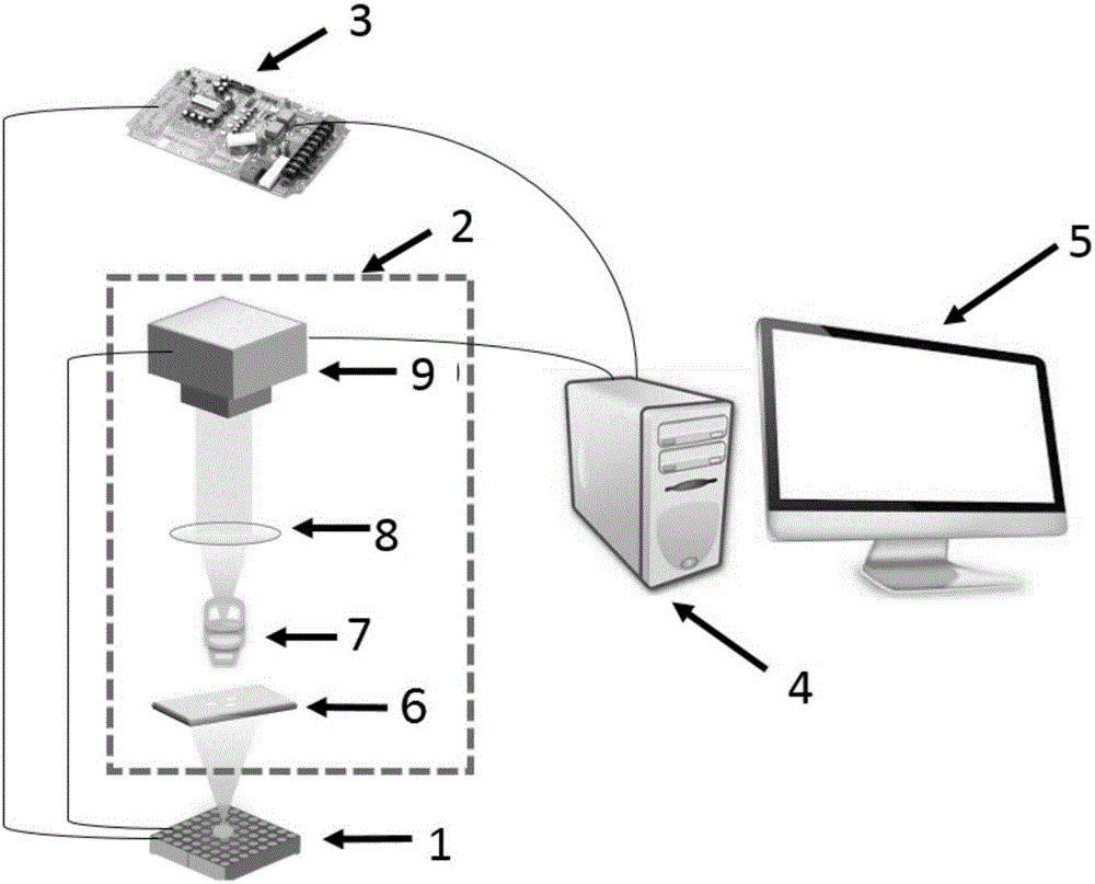
[0026] The multi-mode microscopic imaging method based on programmable LED array illumination of the present invention is realized on a hardware platform based on a programmable LED array microscope. combine figure 1 , the microscope based on programmable LED array mainly includes LED array 1, microscope imaging system 2, circuit control system 3, computer host 4, display 5, and described microscope imaging system 2 includes sample stage 6, microscope objective lens 7, mirror A tube lens 8 and a camera 9 (color or grayscale camera), wherein the light transmitted through the sample stage 6 is collected by the microscope objective lens 7 and imaged on the image plane of the camera 9 after being enlarged by the tube lens 8 . The circuit control system 3 is connected with the LED array 1 , the camera 9 and the computer host 4 respectively. The display 5 is a traditional display (that is, a general CRT or LCD liquid crystal display), and is used for displaying imaging results.

...


PUM


Abstract

The invention discloses a multi-mode microimaging method based on programmable LED array illumination. An LED array used as an illumination light source of a microimaging system is directly installed below a sample carrying bench of the microimaging system and the center of the LED array is located at an optical axis of the microimaging system, thereby realizing phase contrast, optical field imaging, and optical dyeing imaging modes. With the method, dyeing microimaging can be realized flexibly and no additional optical element like an annular diaphragm, a microlens array, and a phase plate and the like needs to be added in an imaging light path of a microscopic, so that the system structure is simplified and the cost is substantially reduced.

Description

technical field [0001] The invention belongs to optical microscopic imaging technology, in particular to a multi-mode microscopic imaging method based on programmable LED array illumination. Background technique [0002] Phase contrast imaging and polarized light imaging are two common microscopic imaging methods, and the corresponding microscopes are called phase contrast microscope and polarized light microscope respectively. Phase contrast microscope, also known as phase contrast microscope, was invented by Dutch scientist Zernike in 1935 (Sheng Fugen. Principle Analysis of Differential Interference Phase Contrast Microscope (Vector Method) [J]. Optical Instruments, 1986, (5).), Microscope for viewing unstained specimens. Phase-contrast microscopy uses the difference in refractive index and thickness between different structural components of the object to convert the optical path difference passing through different parts of the object into the difference in amplitude (...

Claims


Application Information

Patent Timeline
IPC IPC(8): G02B21/06
Inventor 左超陈钱孙佳嵩李加基顾国华张玉珍冯世杰张佳琳胡岩陶天阳张良孔富城张敏亮范瑶林飞
Owner NANJING UNIV OF SCI & TECH
Why Eureka
Try Eureka