Flue gas desulphurization system and method for flue gas desulfurization by means of same

A desulfurization system and flue gas technology, applied in separation methods, chemical instruments and methods, dispersed particle separation, etc., can solve the problems of complex structure, large space occupation and high maintenance cost

Active Publication Date: 2015-12-23
龙创信恒(北京)科技有限公司
View PDF5 Cites 8 Cited by
  • Summary
  • Abstract
  • Description
  • Claims
  • Application Information

AI Technical Summary

Problems solved by technology

However, the disadvantages of the current spray desulfurization towers are as follows: firstly, the spray device needs a high-pressure pump to spray out the circulating desulfurization reaction slurry, so a relatively high injection pressure is required, so the energy consumption of the prepared high-pressure pump is relatively high, and it takes a lot of money. A large amount of electric energy causes energy waste; secondly, the nozzles of the spraying device are relatively easy to block, and because the droplets of the sprayed reaction slurry do not have

Method used


Image

  • Flue gas desulphurization system and method for flue gas desulfurization by means of same
  • Flue gas desulphurization system and method for flue gas desulfurization by means of same
  • Flue gas desulphurization system and method for flue gas desulfurization by means of same

Examples


Embodiment Construction

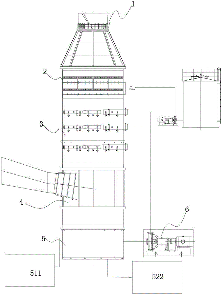
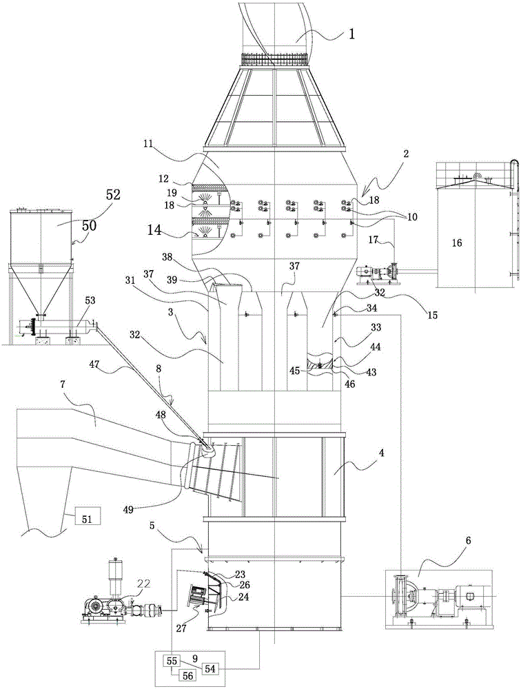
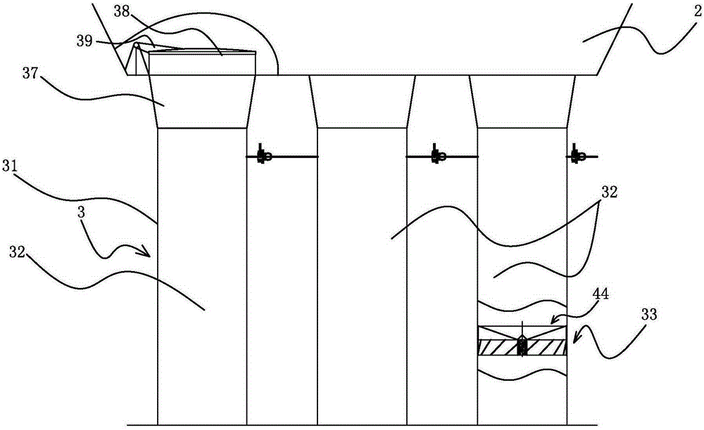
[0056] The following with attached Figure 2 to Figure 18 A flue gas desulfurization system of the present invention and a flue gas desulfurization method using it are further described in detail.

[0057] A flue gas desulfurization system of the present invention, please refer to Figure 2 to Figure 18, including a flue gas desulfurization tower, an ash storage device 50, a gypsum preparation device 9 and an air induction device 51, the ash storage device 50, an induction air device 51 and a gypsum preparation device 9 are all connected to the flue gas desulfurization tower, and the flue gas The desulfurization tower includes a tower body and a smoke exhaust device 1, a mist removal device 2, a swirl reaction device 3, a gas equalization device 4 and a multifunctional liquid collection pool 5 arranged from top to bottom along the tower body. The liquid pool 5 communicates with the cyclone reaction device 3 through the slurry circulation system 6 for pumping the reaction slur...


PUM


Abstract

The invention discloses a flue gas desulphurization system and a method for flue gas desulfurization. The system comprises a flue gas desulphurization tower, an ash storage device, a gypsum preparing device and an air induction device, wherein the flue gas desulphurization tower comprises a tower body, a fume extractor, a defrosting device, a rotational flow reaction device, a gas uniformizing device and a multi-functional collecting reservoir, the fume extractor, the defrosting device, the rotational flow reaction device, the gas uniformizing device and the multi-functional collecting reservoir are communicated from top to bottom in sequence, a flue is provided with a dry powder inlet communicated with a dry powder desulfurizing agent spraying device, the multi-functional collecting reservoir is arranged under the gas uniformizing device, the rotational flow reaction device comprises a rotational flow shell and at least one rotational flow chamber provided with at least one swirler inside, each rotational flow chamber is provided with a circular reaction slurry inlet and communicated with the gas uniformizing device, and each swirler comprises an impeller shell, an impeller center shaft and at least five swirl vanes surrounding the impeller center shaft. By the adoption of the system, flue gas desulphurization effect and degree can be improved, space can be saved, a slurrying pool and a slurry precipitation pool are not needed, maintenance is convenient, cost is low, energy is saved, and environment pollution is avoided.

Description

technical field [0001] The invention relates to a desulfurization device and auxiliary equipment used in desulfurization, in particular to a flue gas desulfurization system. [0002] The present invention also relates to a flue gas desulfurization method, in particular to a flue gas desulfurization method using the aforementioned flue gas desulfurization system. Background technique [0003] With the continuous development of social industry, the degree of industrialization is getting higher and higher, the scale of production is expanding, and more and more flue gas is discharged into the atmosphere. Among the various gaseous pollutants that affect air quality, SO 2 The flue gas has the largest quantity and the greatest impact. It causes acid rain, destroys the ecological environment, and affects people's health. Therefore, before these industrial flue gases are discharged into the atmosphere, they all need to be treated, and the most important one is desulfurization treat...

Claims


Application Information

Patent Timeline
IPC IPC(8): B01D53/83B01D53/80B01D53/50
Inventor 刘志伟徐霄龙高向武焦烨鋆
Owner 龙创信恒(北京)科技有限公司
Why Eureka
Try Eureka