Gantry vertical type numerical control single-head milling machine machining center

A milling machine processing, gantry technology, applied in the direction of metal processing, metal processing equipment, metal processing machinery parts, etc., can solve the problem that the continuous finishing of large and medium-sized parts cannot be applied, and achieve rapid continuous processing, good rigidity, and compact structure Effect

Inactive Publication Date: 2015-12-23
西安宝钢钢材加工配送有限公司
View PDF7 Cites 7 Cited by
  • Summary
  • Abstract
  • Description
  • Claims
  • Application Information

AI Technical Summary

Problems solved by technology

For example, the overall structure of the gantry type boring and milling machine tool is composed of a gantry frame. Functional ram type vertical up and down movement (Z axis), vertical spindle boring and milling cutter head, according to the needs of the core manufacturing fiel

Method used


Image

  • Gantry vertical type numerical control single-head milling machine machining center
  • Gantry vertical type numerical control single-head milling machine machining center
  • Gantry vertical type numerical control single-head milling machine machining center

Examples


Embodiment 1

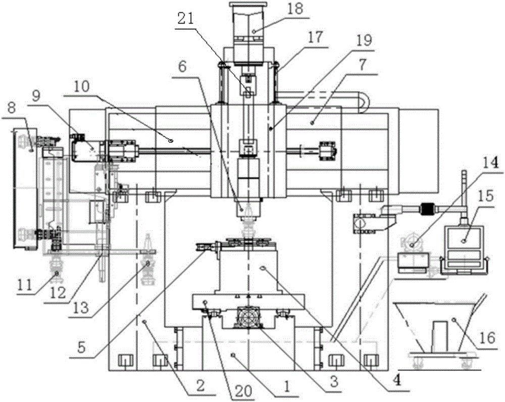
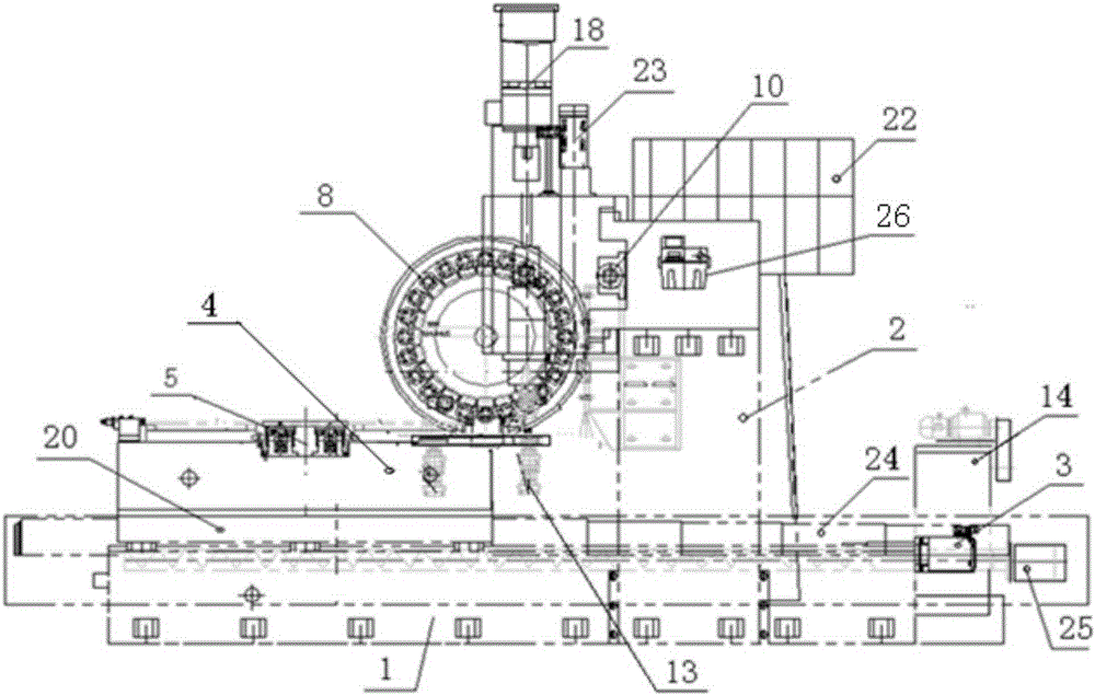
[0028] see figure 1 , figure 2 , image 3 As shown, the gantry vertical CNC single-head milling machine machining center of the present invention includes a base 1, a gantry column 2, an X-axis main slide table 20, a workpiece platform 4, a fixture 5, a spindle milling head 6, a fixed beam 7, a circular Disc cutter magazine 8, numerical control system 15 and other components, the operation of numerical control system 15 is realized through the manipulation screen. An X-axis main slide 20 and an X-axis servo motor 3 and a ball screw for driving the X-axis main slide 20 are arranged above the base 1 .

[0029] A gantry column is arranged on both sides of the base 1, a tool change mechanism 12 is installed above the left side of the gantry column 2, and a fixed beam 7 is arranged above the gantry column, and a cross beam 7 is arranged on the fixed beam 7. CNC slide table, the cross CNC slide table is Y-axis slide table 10 and Z-axis slide table 19, Y-axis slide table 10 and Z...

Embodiment 2

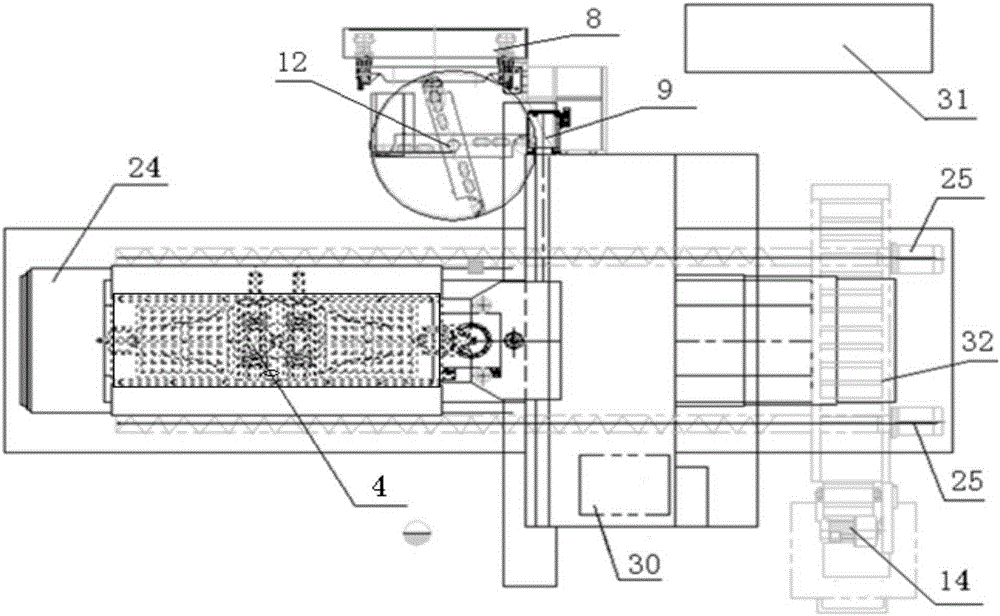
[0036] According to the second embodiment of the present invention, the milling machine processing center also includes a machine tool guide rail protection device, the main guide rail X-axis shield 24 is arranged above the guide rail of the X-axis main slide table 20 above the base 1, and the fixed beam 7 The outer side of the Y-axis guide rail is also provided with a protective cover. Preferably, the protective cover device is a fully enclosed stainless steel telescopic protective cover.

[0037] The machine tool auxiliary device of the present invention also includes a lubricating system, a magnetic automatic chip removal system and a coolant system. The machine tool adopts the centralized lubrication 26 device, and selects the Bechier lubrication station. The milling machine machining center is equipped with a magnetic automatic chip removal system. The chip removal system is composed of auger chip removal channels arranged on both sides of the X-axis main slide table 20. T...


PUM


Abstract

The invention relates to a gantry vertical type numerical control single-head milling machine machining center. The gantry vertical type numerical control single-head milling machine machining center comprises a base, gantry stand columns, a fixed type transverse beam, a cross-shaped numerical control sliding table, an X-axis main sliding table, a workpiece platform, a clamp, a main shaft milling head, a disc tool changer and a numerical control system; the clamp is installed on the workpiece platform of the X-axis main sliding table; and the cross-shaped numerical control sliding table composed of a Y-axis sliding table and a Z-axis sliding table is arranged above the fixed type transverse beam, the special vertical type main shaft milling head is installed in the center of the cross-shaped numerical control sliding table, the disc tool changer is installed on the outer side of the stand column on the left side, and the continuous cutting and machining requirement of complex workpieces can be met through a machine tool under control of the numerical control system. A main shaft is provided with a broach mechanism, and rapid and automatic tool changing can be achieved under matching of a tool hitting cylinder and the tool changer; the main shaft milling head is transmitted through an alternating current servo motor and a ZF reducer casing, operation is stable, and the transmitting torque is large; and after first-time clamping of the workpieces, rough and finish machining of multiple work procedures including boring, milling, drilling and stranding on the workpieces can be automatically completed.

Description

technical field [0001] The invention belongs to the technical field of machinery manufacturing equipment, and in particular relates to a gantry vertical numerical control single-head milling machine processing center applicable to rough and medium-sized parts in automobiles, metallurgy, wind power, ships, coal mine machinery, and engineering machinery. Background technique [0002] At present, the gantry type boring and milling machine is a mechanical processing equipment integrating advanced technologies such as machinery, electricity, and hydraulics. It is suitable for semi-finishing and finishing machining in heavy machinery, locomotives, power generation, machine tools, automobiles, molds, etc. roughing. For example, the overall structure of the gantry type boring and milling machine tool is composed of a gantry frame. Functional ram type vertical up and down movement (Z axis), vertical spindle boring and milling cutter head, according to the needs of the core manufactu...

Claims


Application Information

Patent Timeline
IPC IPC(8): B23Q3/157B23Q3/16B23Q37/00
CPCB23Q3/1572B23Q3/16B23Q37/005
Inventor 曹建良阮志强
Owner 西安宝钢钢材加工配送有限公司
Why Eureka
Try Eureka