
Machine-made charcoal charring and decoking technology and apparatus thereof

A technology of mechanism carbonization and carbonization, which is used in stationary carbonization furnaces, coke ovens, petroleum industry, etc.

Active Publication Date: 2015-12-30
CHONGQING ZHUHAI NEW ENERGY DEV CO LTD
View PDF4 Cites 3 Cited by
  • Summary
  • Abstract
  • Description
  • Claims
  • Application Information

AI Technical Summary

Problems solved by technology

A large amount of gas is produced during the carbonization process, which is not fully utilized, resulting in waste of energy
CN102032553A "A Continuous Rotary Biomass Pyrolysis Carbonization and Boiler Heating Integrated Equipment" discloses a method of using biomass pyrolysis carbonization to generate wood gas, and the high-temperature flue gas generated after combustion provides high-temperature biomass pyrolysis Energy equipment, although the equipment recycles wood gas, but the equipment has the following shortcomings: the gas is easy to condense into solid coke, causing pipeline blockage, polluting equipment and the environment

Method used


Image

  • Machine-made charcoal charring and decoking technology and apparatus thereof
  • Machine-made charcoal charring and decoking technology and apparatus thereof

Examples


Embodiment 1

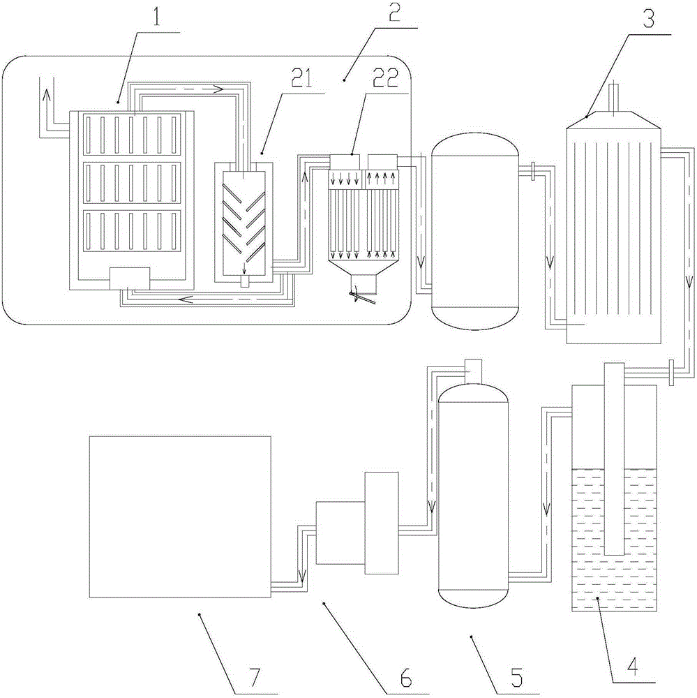
[0015] A mechanism carbonization decoking process, comprising the following steps

[0016] S1) carbonization, carbonizing the biomass raw material in a carbonization furnace;

[0017] S2) Coarse decoking, the wood gas produced in the carbonization process is mixed with impurities, smoke, etc., and part of the smoke and tar are filtered through this step;

[0018] S3) High-voltage electrostatic decoking. The function of the electrostatic decoking device is to use the effect of a strong electric field to make the fine particles such as dust and oil mist in the semi-water gas negatively charged and move to the cathode. After neutralization, they are adsorbed, precipitated and discharged. To achieve the purpose of removal, remove most of the smoke and tar;

[0019] S4) liquid phase separation;

[0020] S5) Activated carbon purification, absorbing residual impurities by activated carbon;

[0021] S6) supercharging, easy to collect after supercharging;

[0022] The process flow ...

Embodiment 2

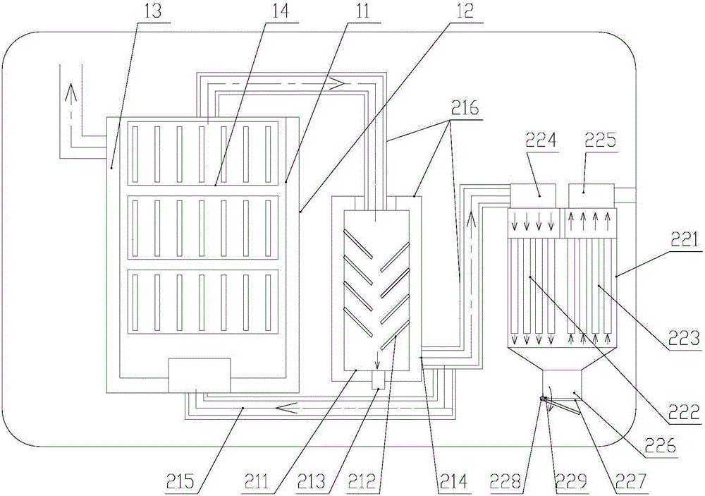
[0024] A mechanical carbonization and decoking device, including a carbonization furnace 1, a rough decoking device 2, a high-voltage electrostatic decoking tower 3, a liquid phase separator 4, an activated carbon purification tower 5, a compressor 6 and a gas storage tank connected sequentially through pipelines 7. Biomass raw materials such as powder or bars made of powder are carbonized in the carbonization furnace 1, and the flue gas generated during the carbonization process passes through the coarse decoking device 2 for coarse dedusting and decoking, and the high-voltage electrostatic decoking tower 3 for fine dedusting and decoking , the liquid phase separator 4 separates the liquid, the activated carbon purification tower 5 absorbs harmful substances, and finally is stored in the gas storage tank 7 after being compressed and boosted by the compressor 6, and the gas in the gas storage tank 7 can be used for generator power generation. Wherein the gas storage tank 7 is ...


PUM


Abstract

The invention discloses a machine-made charcoal charring and decoking technology. The technology comprises the following steps: 1, charring: charring a biomass raw material in a charring furnace; 2, carrying out decoking purification on a gas generated in the charring process; 3, carrying out high-voltage electrostatic decoking; 4, carrying out liquid phase separation; 5, carrying out active carbon purification; and 6, supercharging, and collecting. The invention also discloses an apparatus for realizing the technology. The apparatus comprises the charring furnace, a coarse decoking device, a high-voltage electrostatic decoking tower, a liquid phase separator, an active carbon purifying tower, a compressor and a gas storage tank which are sequentially connected through a pipeline. The technology and the apparatus allow the charred wood gas to be fully purified and especially allow tar to be removed in order to make the charred and decoked charcoal be used in power generation.

Description

technical field [0001] The invention relates to a mechanism carbonization and decoking process and device, belonging to the field of carbon production. Background technique [0002] Mechanism carbonization is to form a porous carbon structure from biomass materials such as wood chips and straws under high temperature and anoxic conditions. A large amount of gas will be produced during the carbonization process, which is not fully utilized, resulting in a waste of energy. CN102032553A "A Continuous Rotary Biomass Pyrolysis Carbonization and Boiler Heating Integrated Equipment" discloses a method of using biomass pyrolysis carbonization to generate wood gas, and the high-temperature flue gas generated after combustion provides high-temperature biomass pyrolysis Energy equipment, although the equipment recycles wood gas, but the equipment has the following shortcomings: the gas is easy to condense into solid coke, causing pipeline blockage, polluting equipment and the environm...

Claims


Application Information

Patent Timeline
IPC IPC(8): C10B53/02C10B1/02C10K1/00C10K1/02C10K1/04C10K1/32
CPCY02E50/10
Inventor 唐勇军唐忠良
Owner CHONGQING ZHUHAI NEW ENERGY DEV CO LTD
Learn More