Sludge treatment device

A technology of sludge treatment and treatment cylinder, applied in the direction of sludge treatment, water/sludge/sewage treatment, chemical instruments and methods, etc., can solve air and environmental pollution, the overall technical route of national sludge treatment and disposal is not clear enough, Problems such as not being properly dealt with can achieve the effect of overcoming secondary pollution and alleviating the contradiction between sludge production and sludge treatment capacity lag

Active Publication Date: 2016-01-06
徐明好
View PDF5 Cites 3 Cited by
  • Summary
  • Abstract
  • Description
  • Claims
  • Application Information

AI Technical Summary

Problems solved by technology

The three wastes produced in this incineration process still continue to produce secondary pollution. Not only have they not been treated well, but they also need to be supplemented with external fuels. New sources of pollution such as dust and dioxins produced in the incineration process will cause serious damage to the air and the environment. new pollution
At present, there are many factors restricting the construction of sludge treatment and disposal facilities, but the overall technical route of national sludge treatment and disposal is not clear enough is one of the important restricting factors

Method used


Image

  • Sludge treatment device
  • Sludge treatment device
  • Sludge treatment device

Examples


Embodiment 1

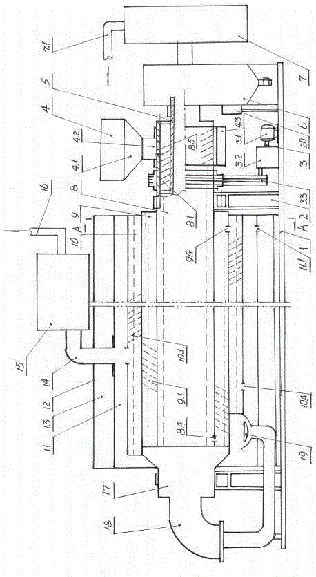
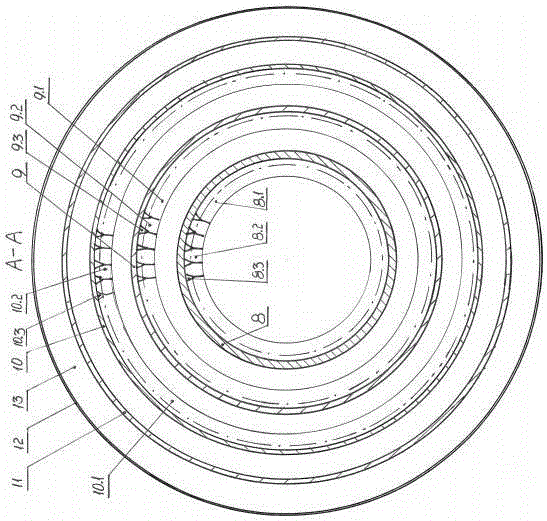
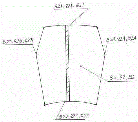
[0028] A kind of sludge treatment device of embodiment 1 of the present invention (see figure 1 , figure 2 , image 3 ), including machine base 1, sludge treatment drums 8, 9, 10, 11, power drive mechanism 3, output pipelines 5, 14, 18 and machine cover 12, and the sludge treatment device described in it includes heavy metal treatment drums 8. The carbonization drum 9 and the fixed carbon combustion drum 10 are composed of three coaxial sets from the inside to the outside. The helixes 8.1, 9.1, and 10.1 on the inner side of the cylinder are arranged opposite to each other, and the cylinder at the end of the helix 8.1, 9.1, and 10.1 The wall is provided with discharge port 8.4, 9.4, 10.4 of the sludge treatment drum constituted by the spiral drum, the two ends of the drum are respectively provided with a supporting device 2; the heavy metal processing drum 8 of the sludge processing drum and the carbonization drum 9 form a The dislocation structure is set, and a power drive ...

Embodiment 2

[0037] A kind of sludge treatment device of embodiment 2 of the present invention (see figure 1 , figure 2 , image 3 ), including machine base 1, sludge treatment drums 8, 9, 10, 11, power drive mechanism 3, output pipelines 5, 14, 18 and machine cover 12, and the sludge treatment device described in it includes heavy metal treatment drums 8. The carbonization drum 9 and the fixed carbon combustion drum 10 are composed of three coaxial sets from the inside to the outside. The helixes 8.1, 9.1, and 10.1 on the inner side of the cylinder are arranged opposite to each other, and the cylinder at the end of the helix 8.1, 9.1, and 10.1 The wall is provided with discharge port 8.4, 9.4, 10.4 of the sludge treatment drum constituted by the spiral drum, the two ends of the drum are respectively provided with a supporting device 2; the heavy metal processing drum 8 of the sludge processing drum and the carbonization drum 9 form a The dislocation structure is set, and a power drive ...

Embodiment 3

[0046] A kind of sludge treatment device of embodiment 3 of the present invention (see figure 1 , figure 2 , image 3 ), including machine base 1, sludge treatment drums 8, 9, 10, 11, power drive mechanism 3, output pipelines 5, 14, 18 and machine cover 12, and the sludge treatment device described in it includes heavy metal treatment drums 8. The carbonization drum 9 and the fixed carbon combustion drum 10 are composed of three coaxial sets from the inside to the outside. The helixes 8.1, 9.1, and 10.1 on the inner side of the cylinder are arranged opposite to each other, and the cylinder at the end of the helix 8.1, 9.1, and 10.1 The wall is provided with discharge port 8.4, 9.4, 10.4 of the sludge treatment drum constituted by the spiral drum, the two ends of the drum are respectively provided with a supporting device 2; the heavy metal processing drum 8 of the sludge processing drum and the carbonization drum 9 form a The dislocation structure is set, and a power drive me...


PUM


Abstract

The invention discloses a sludge treatment device, and belongs to the technical field of sludge treatment. According to the technical scheme, the sludge treatment device comprises a machine base, a sludge treatment drum, a power driving mechanism, an output pipeline and a machine cover. The sludge treatment device is characterized in that the sludge treatment drum at least composed of three spiral barrels is included, the spiral barrels comprise the heavy metal treatment drum, the carbonization drum and the fixed carbon combustion drum which are coaxially installed into a whole in a sleeving mode from inside to outside, the spiral lines of the inner sides of barrel bodies are oppositely arranged, the barrel walls at the tail ends of the spiral lines are provided with discharge holes, and the two ends of the sludge treatment drum are each provided with a support device. Compared with the prior art, the sludge treatment device has the advantages of being novel, reliable in technical scheme, free of secondary pollution, high in investment efficiency and capable of rapidly achieving effects and has the outstanding substantive features and significant improvement.

Description

technical field [0001] The invention relates to the technical fields of chemical industry and environmental protection, in particular to the technical field of a sludge treatment device used for sludge, especially for urban sewage treatment plants. Background technique [0002] In recent years, with the rapid improvement of my country's sewage treatment capacity, the amount of sludge has also increased significantly. As of the end of March 2013, as far as sludge from urban sewage treatment plants is concerned, a total of 3,451 urban sewage treatment plants have been built in cities and counties across the country, with a sewage treatment capacity of about 145 million cubic meters per day, and annual production of sewage with a water content of 80%. There are more than 35 million tons of sludge, and there are about 120 sewage treatment plants increasing each year. According to statistics, about 80% of sewage plants have sludge concentration and dehydration facilities, which ...

Claims


Application Information

Patent Timeline
IPC IPC(8): C02F11/00
Inventor 徐明好
Owner 徐明好
Why Eureka
Try Eureka