Downward trendline bunching SAR radar positioning method based on imaging matching

A radar positioning and radar technology, which is applied in the field of image matching-based spotlight SAR radar positioning in descending orbits, can solve problems such as limited application range, inapplicability, and large errors in inertial navigation data, so as to improve robustness and good application value , the effect of high positioning accuracy

Active Publication Date: 2016-01-13
XIDIAN UNIV
View PDF5 Cites 9 Cited by
  • Summary
  • Abstract
  • Description
  • Claims
  • Application Information

AI Technical Summary

Problems solved by technology

[0003] Yanying et al. mentioned the SAR platform positioning method based on inertial navigation data in the document "Missile-borne synthetic aperture radar imaging processing and positioning error analysis". Although the method is simple, the error of the inertial navigation data used in China is generally large, resulting in low positioning accuracy of the SAR platform
[0004] Li Yachao and others mentioned in the document "Milestone Positioning Method and Analysis in SAR Terminal Guidance" that using three different fixed target scenarios in the terminal guidance of missiles and the known slant distance and ground distance of the three fixed target scenarios The parameters are used to locate the missile body; although this method analyzes the influence of missile regular flight and missile irregular flight on the positioning accuracy, this positioning method is only applicable to the situation where the SAR platform works in the frontal and side-looking strip mode. For large squint Spotlight mode, this method does not apply
[0005] Li Yachao and others mentioned a squint SAR platform positioning algorithm based on scene matching in "Feasibility Research on High-speed SAR Platform Positioning and Velocity Measurement under High-precision Scene Matching". Alignment with the squint SAR platform for positioning and speed measurement; although the positioning accuracy of this method is high, it will still be affected by the position of the ground matching point. When the registration error and estimation error are determined, or the position of the ground matching point is close, the Decreases the positioning accuracy of the squint SAR platform
[0006] Yang Libo and others established a positioning model based on the distance difference and Doppler difference of matching points in "Synthetic Aperture Radar Scene Matching Guided Missile Positioning". The angle between the velocity vector and the center slope distance vector is not on the same plane as the angle between the velocity vector and the instantaneous slope distance vector, that is, the positioning model of distance difference and Doppler difference cannot be used for angle measurement positioning
In addition, when the polar format algorithm (PolarFormat Algorithm, PFA) is used for SAR imaging in spotlight mode, the oblique plane SAR imaging obtained is a two-dimensional wavenumber domain map, which makes the Doppler angle measurement formula unable to be used directly, and also limits the method scope of application

Method used


Image

  • Downward trendline bunching SAR radar positioning method based on imaging matching
  • Downward trendline bunching SAR radar positioning method based on imaging matching
  • Downward trendline bunching SAR radar positioning method based on imaging matching

Examples


Embodiment Construction

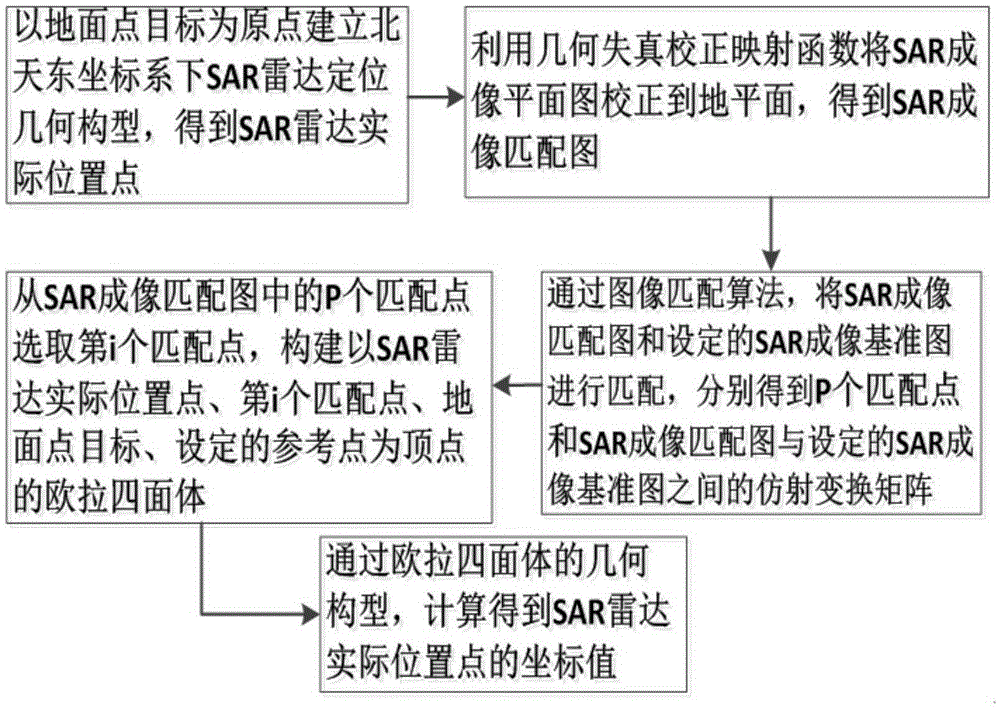
[0025] refer to figure 1 , is a schematic flowchart of an image matching-based descending orbit spotlight SAR radar positioning method of the present invention, and a schematic flowchart of the image matching-based descending orbit spotlight SAR radar positioning method, including the following steps:

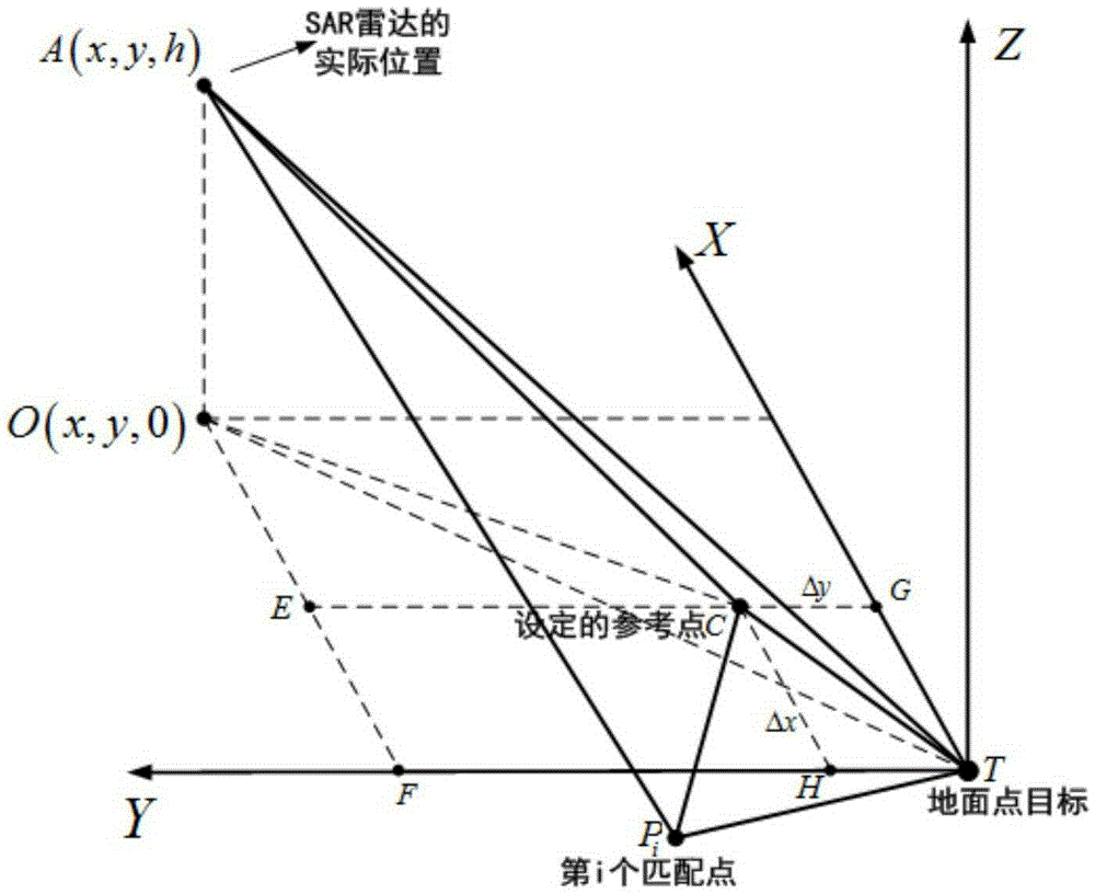
[0026] Step 1: Taking the ground point target T as the origin, and based on the descending orbit of the SAR radar, establish the geometric configuration of the missile body positioning in the north eastern coordinate system, and obtain the SAR imaging plane image of the ground point target T in the imaging plane and the SAR radar in turn. The actual location of point A.

[0027] Specifically, refer to figure 2, which is a schematic diagram of the positioning geometry of the missile body under the North Tiandong coordinate system established with the ground point target T as the origin; among them, A is the actual position of the SAR radar; It can be seen from the model that ...


PUM


Abstract

The invention discloses a downward trendline bunching SAR radar positioning method based on imaging matching. The method includes the steps: taking a ground point target as an original point, establishing a geometrical configuration of missile location in an East-North-Up coordinate system on the basis of a downward trendline of SAR radar, and sequentially obtaining an SAR imaging plane image of the ground point target on an imaging plane and the actual position A of SAR radar; obtaining an SAR imaging matched image by means of a geometrical distortion correction mapping function between the imaging plane and a ground plane; obtaining P matching points through an image matching algorithm, and obtaining an affine transformation matrix between the SAR imaging matched image and a set SAR imaging reference image according to the P matching points; constructing an Euler tetrahedron by means of the affine transformation matrix; and according to the set sampling frequency and distance unit numbers of the SAR radar, obtaining the distance between the SAR radar and the ground point target T, the distance between the SAR radar and a set reference point C and the distance between the SAR radar and the p matching point Pp, and calculating the coordinate value of the actual position A of the SAR radar.

Description

technical field [0001] The invention belongs to the technical field of radar image target positioning, in particular to a descending orbit spotlight SAR radar positioning method based on image matching, which is suitable for providing accurate position information for missile body deviation correction. Background technique [0002] In the terminal guidance stage of the missile, due to inertial navigation error, there is a large deviation between the actual position of the missile body and the position indicated by the inertial navigation, which affects the accurate positioning of the missile seeker to the target and cannot meet the traditional optical missile seeker. The accuracy requirement of shift change reduces the precision strike performance of the missile. The missile-borne synthetic aperture radar (Synthetic Aperture Radar, SAR) seeker adopts the spotlight SAR imaging mode in the descending section of the missile. The SAR reference image is matched and positioned to...

Claims


Application Information

Patent Timeline
Patent Type & Authority Applications(China)
IPC IPC(8): G01S7/41G01S13/90G06T3/00
CPCG01S7/415G01S13/9029G06T3/0006G01S13/9004G01S13/9027G01S13/9052
Inventor 李亚超邓欢项宇泽全英汇
Owner XIDIAN UNIV
Why Eureka
Try Eureka