Super surface quarter wave plate based on surface plasmon polariton

A surface plasmon and metasurface technology, applied in optical elements, polarizing elements, optics, etc., can solve the problems of large thickness, difficult processing, and narrow waveband, and achieve the effect of thin thickness, low processing difficulty, and wide waveband.

Active Publication Date: 2016-01-13
JIANGSU INST OF ADVANCED SEMICON CO LTD
View PDF3 Cites 11 Cited by
  • Summary
  • Abstract
  • Description
  • Claims
  • Application Information

AI Technical Summary

Problems solved by technology

[0006] The purpose of the present invention is to provide a metasurface quarter-wave plate based on surface plasmons, which solves the existing problems of large thickness, difficult processing and narrow waveband

Method used


Image

  • Super surface quarter wave plate based on surface plasmon polariton
  • Super surface quarter wave plate based on surface plasmon polariton
  • Super surface quarter wave plate based on surface plasmon polariton

Examples


Embodiment 1

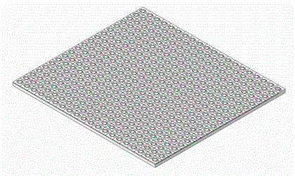
[0048] Embodiment one: see figure 1 As shown, a metasurface quarter-wave plate based on surface plasmons, the wave plate includes a rectangular substrate and a silver film arranged on the rectangular substrate, the silver film is composed of a number of periodic arrays of aperture units, each The aperture units are equipped with two horizontal apertures symmetrical up and down and two longitudinal apertures symmetrical about the left and right centers. There is an intersection.

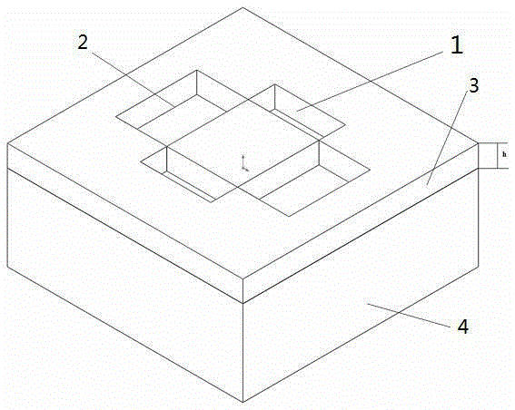
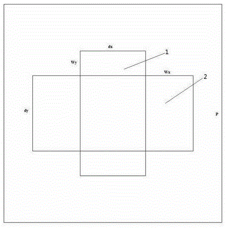
[0049] Such as figure 2 , image 3 As shown, the basic structure of the aperture unit includes a silver film with an aperture and a corresponding substrate, and the center-to-center distance between adjacent aperture units is P, that is, the period of the aperture unit can also be represented by P, that is, the side length of the aperture unit is p.

[0050] The working wavelength of the present invention is 1400nm to 1700nm.

[0051] In this embodiment, the rectangular substrate is a rectangula...

Embodiment 2

[0059] Embodiment 2: The parameters selected in this embodiment are dx=165nm, dy=190nm, P=550nm, Wx=120nm, Wy=60nm, h=50nm, and the maximum aspect ratio is 0.83, see Figure 18 As shown, the schematic diagram of the phase and phase difference curves in the X direction and Y direction under the irradiation of the transmitted light wavelength 1400-1700nm, where the solid line is the phase difference between the X-direction component and the Y-direction component of the transmitted light, and the dotted line is the Y-direction of the transmitted light The phase of the component, the dotted line is the phase of the X-direction component of the transmitted light, it can be calculated that when the wavelength λ=1550nm, the phase difference is 1.472, see Figure 19 As shown, it is a schematic diagram of the transmittance curve of the second embodiment under the irradiation of the transmitted light wavelength 1400-1700nm. It can be seen that when the transmitted light wavelength λ=1550...

Embodiment 3

[0060] Embodiment 3: The parameters selected in this embodiment are dx=155nm, dy=200nm, P=550nm, Wx=120nm, Wy=60nm, h=68nm, and the maximum aspect ratio is 1.13, see Figure 20 As shown, the schematic diagram of the phase and phase difference curves in the X direction and Y direction under the irradiation of the transmitted light wavelength 1400-1700nm, where the solid line is the phase difference between the X-direction component and the Y-direction component of the transmitted light, and the dotted line is the Y-direction of the transmitted light The phase of the component, the dotted line is the phase of the X-direction component of the transmitted light, it can be calculated that when the wavelength λ=1550nm, the phase difference is 1.601, see Figure 21 As shown, it is a schematic diagram of the transmittance curve of the second embodiment under the irradiation of the transmitted light wavelength 1400-1700nm. It can be seen that when the transmitted light wavelength λ=1550...


PUM


Abstract

The invention discloses a super surface quarter wave plate based on surface plasmon polariton. The wave plate comprises a rectangular base and a silver film which is arranged on the rectangular base. The silver film is composed of multiple periodic aperture units which are arranged in matrixes. Each aperture unit is provided with two transverse apertures which are centrally symmetrical in a vertical direction and two longitudinal apertures which are centrally symmetrical in a left-and-right direction. The extension line of the internal side of the transverse apertures has no intersection point with the longitudinal apertures. The extension line of the internal side of the longitudinal apertures has no intersection point with the transverse apertures. The super surface quarter wave plate based on the surface plasmon polariton has advantages of being simple in structure, easy to integrate, low in thickness and low in processing difficulty so that the super surface quarter wave plate based on the surface plasmon polariton has great application value in an optical sensing system, an advanced nano-photonic device and an integrated optical system.

Description

technical field [0001] The invention relates to a metasurface quarter-wave plate based on surface plasmons, belonging to the technical field of optical elements. Background technique [0002] In the prior art, controlling the polarization state of light is very important in the field of light research and application. At present, there are mainly two methods for nanoscale optical manipulation. The first method is based on photonic crystals, by controlling the internal structure of photonic crystals to regulate the optical transmission path, so as to realize the transmission of optical information, modulation and optical interconnection, etc., such as nano-microcavities, optical waveguides, optical splitting devices, etc., but currently Most photonic crystals are almost three-dimensional structures, which are very difficult to design and prepare. The second method is to control the propagation of surface plasmon polaritons (SPP). Surface plasmon polaritons are generated on t...

Claims


Application Information

Patent Timeline
Patent Type & Authority Applications(China)
IPC IPC(8): G02B5/30
CPCG02B5/30G02B5/3083
Inventor 王钦华钱沁宇
Owner JIANGSU INST OF ADVANCED SEMICON CO LTD
Why Eureka
Try Eureka