A Simultaneous Desulfurization and Denitrification Process Based on Electrolytic Regeneration for Iron Removal in Flue Gas and Ammonia

An electrolytic regeneration, desulfurization and denitrification technology, applied in the field of flue gas desulfurization and denitrification technology, can solve the problems of large consumption of iron scraps, easy corrosion of iron scraps, affecting conversion efficiency, etc., and achieves low investment cost and operating cost, and desulfurization and denitrification effect. Good, improve the effect of reaction efficiency

Active Publication Date: 2017-09-05
武汉武钢绿色城市技术发展有限公司
View PDF6 Cites 0 Cited by
  • Summary
  • Abstract
  • Description
  • Claims
  • Application Information

AI Technical Summary

Problems solved by technology

[0003] In the iron removal step, alkali needs to be added to adjust the pH value, so that a large amount of alkali metal ions are brought into the concentrated solution into the absorption solution, which increases the production cost and is not conducive to the subsequent crystallization of ammonium sulfate, affecting the quality of desulfurization products
[0004] There are following problems in adopting the iron filings method in the regeneration step: (1) because the absorption liquid is acidic, the iron filings are easily corroded, resulting in a large consumption of iron filings, and the concentration of iron ions in the absorption liquid is too high, which not only increases the cost of iron removal, but also Affect the quality of desulfurization and denitrification by-products; (2) Since the elemental iron in the iron filings is oxidized and corroded into the solution, the pH value of the absorption solution increases, resulting in the weakening of the regenerative reduction ability of the iron filings to the complexing agent
In order to ensure the denitrification efficiency, acid needs to be added to the system, resulting in a further increase in denitrification costs
(3) The consumption of iron filings is relatively large, and a large amount of elemental iron is oxidized into the absorption liquid. Since the pH value of the absorption liquid is controlled above 5.0, the absorption liquid contains a large amount of ferric hydroxide colloid (suspended matter), which will lead to circulation The wear of the impeller of the pump is increased, and it will also cause the nozzle and pipeline to block
(4) Since iron filings are filled in the closed regeneration tower, and the consumption of iron filings is continuous, continuous replenishment of iron filings cannot be realized
[0010] (1) For the reaction system with good electrochemical reversibility between the reactant and the product, the existing electrolysis device will cause repeated conversion between the reactant and the product in the electrolysis reactor, which not only affects the conversion efficiency, but also waste of electricity;
[0011] (2) The existing electrolysis device cannot effectively use the flow of the electrolyte itself to provide a large turbulent force for rapid renewal of the reactants on the electrode surface, and the electrochemical reaction speed is relatively slow, thereby reducing the reaction conversion rate;
[0012] (3) For complex reaction systems containing side reactions, existing electrolysis devices cannot effectively remove electrochemical reaction products that cause side reactions in a timely manner;
[0013] (4) The existing electrolysis device has a complex structure and a large footprint

Method used


Image

  • A Simultaneous Desulfurization and Denitrification Process Based on Electrolytic Regeneration for Iron Removal in Flue Gas and Ammonia
  • A Simultaneous Desulfurization and Denitrification Process Based on Electrolytic Regeneration for Iron Removal in Flue Gas and Ammonia
  • A Simultaneous Desulfurization and Denitrification Process Based on Electrolytic Regeneration for Iron Removal in Flue Gas and Ammonia

Examples


Embodiment Construction

[0054] Below in conjunction with accompanying drawing, the present invention will be further explained:

[0055] Denitration process:

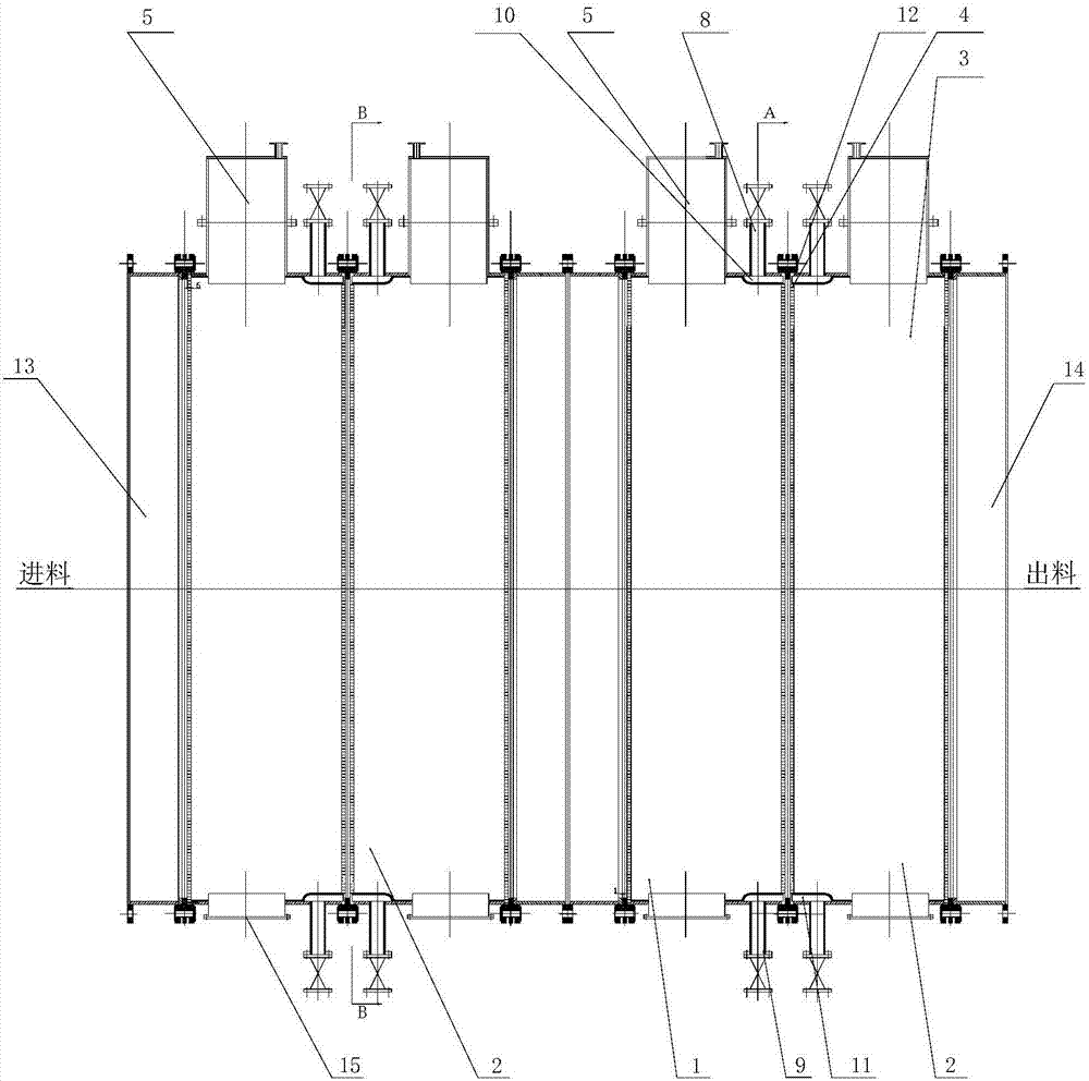
[0056] see Image 6 , after the flue gas is pressurized, it is sent into the concentration tower 16 to contact and react with the concentrated liquid in the tower. The concentrated liquid is sent to the ammonium sulfate crystallization system 21 to obtain ammonium sulfate crystals after being deironed by the first electrolytic reactor 18, and the absorbed liquid after the partial reaction at the bottom of the absorption tower 17 is regenerated by the second electrolytic reactor 19 and then sent to the regeneration slurry tank 20 , the absorption liquid in the regenerated slurry tank is sent back to the absorption tower 17 as a circulating absorption liquid.

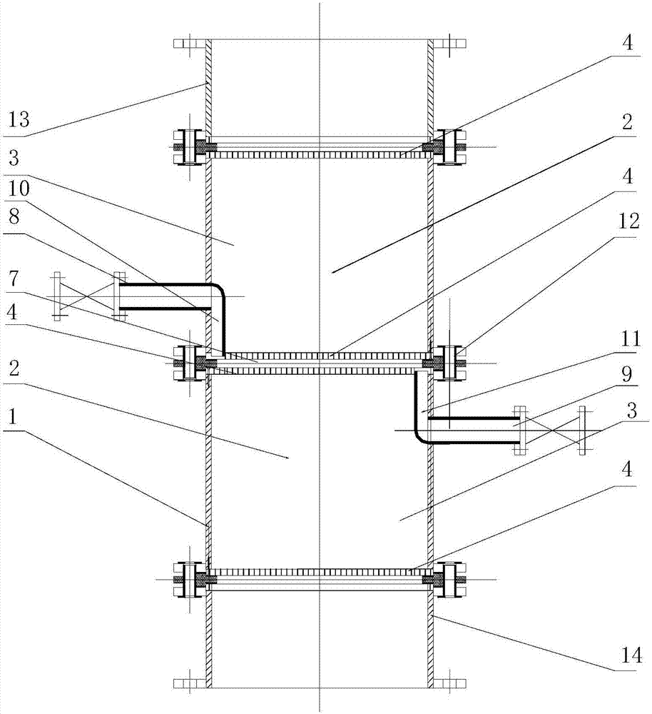
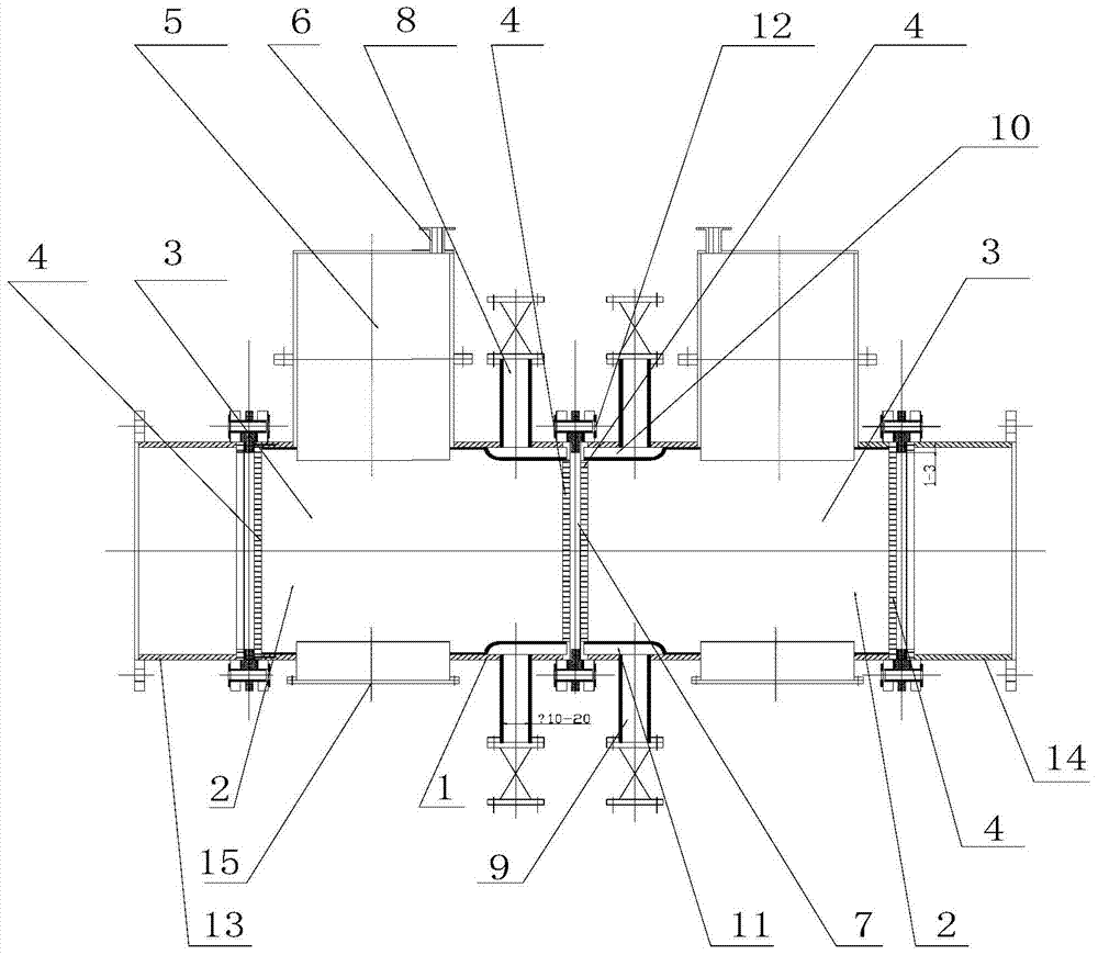
[0057] The structure of the first electrolysis reactor 18 and the second electrolysis reactor 19 can be a vertical or horizontal reactor with a reaction unit,

[0058] Among them, see ...


PUM

PropertyMeasurementUnit
widthaaaaaaaaaa
particle sizeaaaaaaaaaa
pore sizeaaaaaaaaaa

Abstract

The invention discloses a flue gas ammonia synchronous desulfurization and denitrification process based on electrolytic regeneration to remove iron, which solves the problem of low regeneration efficiency of absorption liquid in the existing desulfurization and denitrification process. The technical scheme includes that after the flue gas is pressurized, it is sent to the concentration tower to contact and react with the concentrated liquid in the tower. After iron removal by the first electrolytic reactor, it is sent to the ammonium sulfate crystallization system. The absorbed liquid after partial reaction at the bottom of the absorption tower is regenerated and returned to the upper part of the absorption tower as a circulating absorption liquid. The concentrated liquid first enters the first electrolytic reactor The anode chamber in the reaction unit undergoes an oxidation reaction, and then enters the cathode chamber to undergo a reduction reaction; the reacted electrolyte is discharged from the short outlet pipe of the reactor and sent to the ammonium sulfate crystallization system. The invention has the advantages of simple method, low investment cost and operation cost, high conversion efficiency, good iron removal effect, and good desulfurization and denitrification effect.

Description

technical field [0001] The invention relates to a flue gas desulfurization and denitrification process in the field of energy saving and environmental protection, in particular to a flue gas ammonia synchronous desulfurization and denitrification process based on electrolytic regeneration to remove iron. Background technique [0002] Wet flue gas synchronous desulfurization and denitrification technology, especially wet ammonia-complexation synchronous desulfurization and denitrification technology, has been highly valued by the industry due to its advantages of high desulfurization efficiency, low investment, low water consumption, effective use of by-products, and no secondary pollution. Fe(II)EDTA has a good complexing effect on NO and high denitrification efficiency. For example, the patent application with the publication number 104226095A and the title of the invention is "Synchronous denitrification process based on flue gas wet ammonia desulfurization", which can real...

Claims


Application Information

Patent Timeline
Patent Type & Authority Patents(China)
IPC IPC(8): B01D53/78B01D53/60B01D53/96B01D53/73C01C1/24
Inventor 吴高明康凌晨卢丽君
Owner 武汉武钢绿色城市技术发展有限公司
Why Eureka
Try Eureka