
A directional flow electrolysis process

A directional flow and process technology, applied in the field of electrolysis process, can solve the problems of inability to effectively remove electrochemical reaction products in time, complex structure of the electrolysis device, slow electrochemical reaction speed, etc. rate effect

Inactive Publication Date: 2017-12-08
WUHAN UNIV OF SCI & TECH +1
View PDF10 Cites 0 Cited by
  • Summary
  • Abstract
  • Description
  • Claims
  • Application Information

AI Technical Summary

Problems solved by technology

[0013] (1) For the reaction system with good electrochemical conversion reversibility between the reactant and the product, the existing electrolysis process will cause the repeated conversion between the reactant and the product in the electrolysis reactor, which not only affects the conversion efficiency, but also waste of electricity;
[0014] (2) The existing electrolysis process cannot effectively use the flow of the electrolyte itself to provide a large turbulent force for rapid renewal of the reactants on the electrode surface, and the electrochemical reaction speed is relatively slow, thereby reducing the reaction conversion rate;
[0015] (3) For complex reaction systems containing side reactions, the existing electrolysis process cannot effectively remove the electrochemical reaction products that cause side reactions in a timely manner;
[0016] (4) The electrolysis device used in the existing electrolysis process has a complex structure and a large footprint

Method used


Image

  • A directional flow electrolysis process
  • A directional flow electrolysis process
  • A directional flow electrolysis process

Examples


Embodiment 1

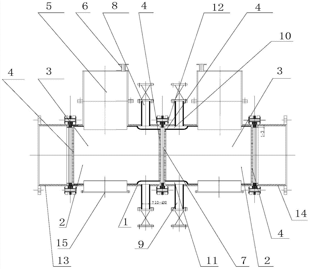
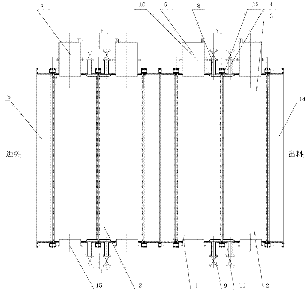
[0048] see figure 2 , the reactor in this embodiment is horizontal, one end of the cylinder 1 is provided with an inlet connection short pipe 13, and the other end is provided with an outlet connection short pipe 14, and a reaction unit is arranged in the cylinder body, which consists of two mutually insulated electrode chambers 2 It consists of a cathode chamber and an anode chamber respectively. The electrode chamber 2 is composed of the area surrounded by the porous plate electrodes 4 at both ends and the corresponding cylinder 1. The electrode chamber 2 is filled with a conductive electrode material 3. The electrode material 3 filled in the electrode chamber is granular activated carbon, coal coke, petroleum coke or corrosion-resistant metal shavings or metal pellets modified by noble metal salts, with a particle size of 8-20mm (the particle size of the electrode material should be larger than that of the porous plate electrode aperture). Both ends of the electrode chamb...

Embodiment 2

[0057] see Figure 5 , the electrode chamber 2 is made up of a mesh structure 16 made of conductive material, the conductive material can be made of lead, platinum, titanium, graphite and other materials with good conductivity and strong corrosion resistance, and its porosity is controlled at 0.7-0.9. There is no porous plate electrode 4 and the filled electrode material 3, and the rest of the structure is the same as in Example 1. The electrolyte is the concentrated solution of the concentration tower in the flue gas wet ammonia-complex absorption synchronous desulfurization and denitrification system.

[0058] work process:

[0059] The physical parameters and related composition of the concentrated liquid from the concentration tower in the flue gas wet ammonia-complex absorption synchronous desulfurization and denitrification system are as follows:

[0060] pH value: 4.0~5.0;

[0061] Ammonium sulfate concentration: 30-45%;

[0062] EDTA-Fe(Ⅱ)+EDTA-Fe(Ⅲ)concentration: ...

Embodiment 3

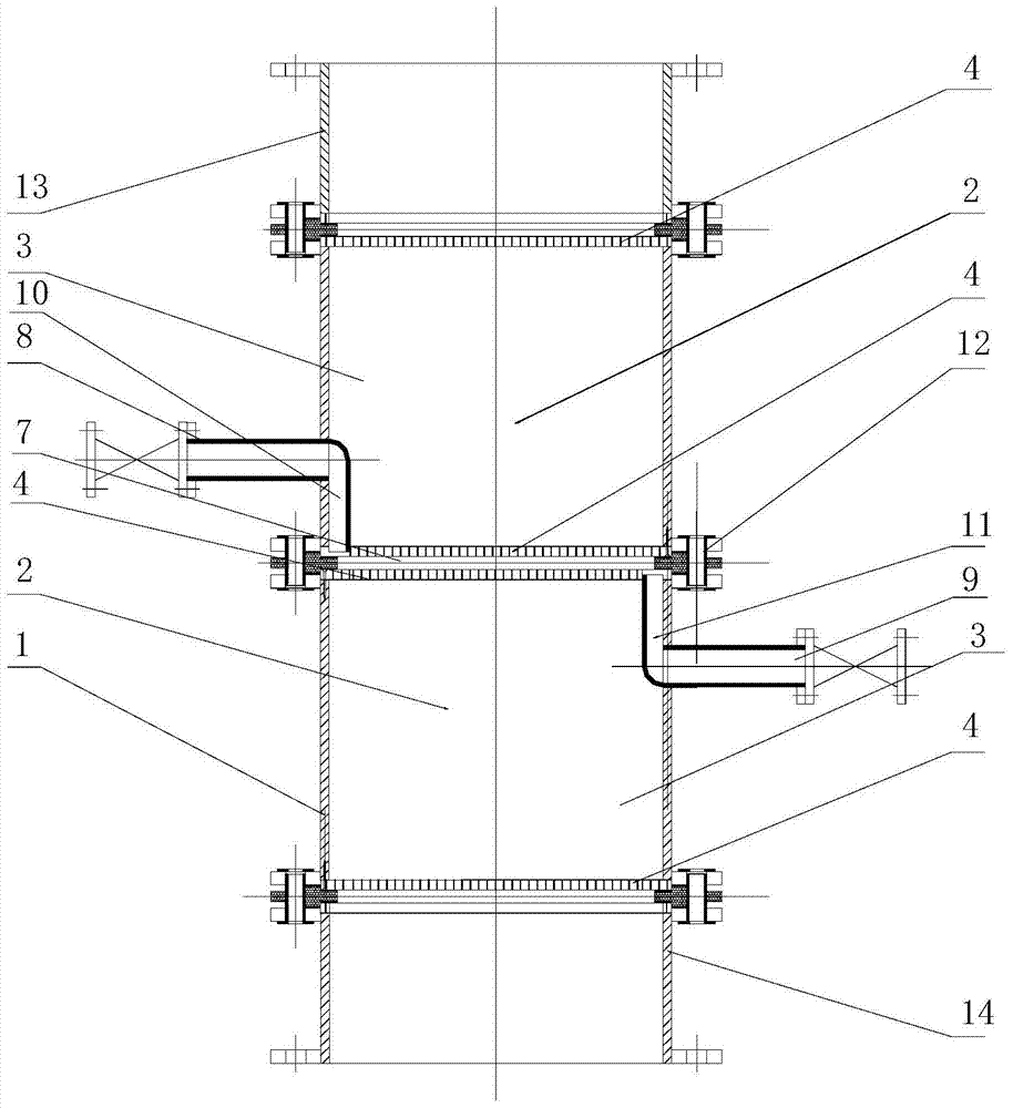
[0084] see figure 1 , the reactor in this embodiment is vertical, and its basic structure is the same as that of the horizontal type in Example 1. The upper layer is the cathode chamber, and the lower layer is the anode chamber. Export 15, all the other are with embodiment 1.

[0085] crafting process:

[0086] The source of the electrolyte is the same as in Example 1, and the reaction process is the same as in Example 1. The electrolyte enters the reactor from the inlet connection short pipe 13 at the bottom of the reactor, flows directionally from bottom to top, and passes through the anode chamber and the cathode chamber successively from the top of the reactor. Outlet connects short pipe 14 to flow out, and all the other are with embodiment 1. Iron removal efficiency is 90%.


PUM

PropertyMeasurementUnit
widthaaaaaaaaaa
particle sizeaaaaaaaaaa
pore sizeaaaaaaaaaa

Abstract

The invention discloses a directional flow electrolysis process, which solves the problems of low conversion rate of reactants, high energy consumption, poor adaptability and the like existing in the existing electrolysis process. The technical solution includes sending the electrolyte solution into the electrolysis reactor to carry out the electrolysis reaction. The electrolyte solution first enters one of the electrode chambers in the electrolysis reactor, and after completing the electrochemical oxidation or reduction reaction, flows through the gap between the two electrode chambers and then Enter the next electrode chamber with opposite polarity to carry out electrochemical reduction or oxidation reaction, and the reacted electrolyte flows out of the electrolytic reactor. The invention has the advantages of simple process, low investment cost and operation cost, high conversion efficiency, and is suitable for electrolytes with various properties.

Description

technical field [0001] The invention relates to an electrolysis process, in particular to a directional flow electrolysis process. Background technique [0002] In the traditional electrolysis process, the electrolyte flows in the area enclosed by the cathode and anode of the reactor and the reactor separator and electrochemical reaction occurs on the electrode surface. For some reaction systems with good reversibility in the electrochemical conversion between reactants and products, two reaction chambers are often separated by a membrane between the cathode and the anode to prevent the reaction products from entering the other reaction chamber. . For the reaction system with good reversibility in the electrochemical conversion between the reactant and the product, it can save power consumption and increase the conversion rate of the reactant. However, due to the existence of the separation membrane, the structure of the reactor is complicated, the manufacturing cost of th...

Claims


Application Information

Patent Timeline
Patent Type & Authority Patents(China)
IPC IPC(8): C25B3/10C25B3/29
Inventor 吴高明姚茜周尽晖韩军卫书杰
Owner WUHAN UNIV OF SCI & TECH
Learn More