Welding structure for inner container longitudinal seam of stainless steel gas cylinder and welding method

A welding structure and welding method technology, applied in welding connection methods, welding/welding/cutting items, welding equipment, etc., can solve the problem of high technical level requirements of welding operators, high post-investment and maintenance costs, and plasma arc welding equipment. Expensive and other problems, to achieve the effect of low cost of use and maintenance, prevention of welding hot crack defects, and prevention of incomplete fusion and incomplete penetration defects

Active Publication Date: 2016-01-20
ANHUI DAPAN SPECIAL EQUIP VEHICLE CO LTD
View PDF7 Cites 23 Cited by
  • Summary
  • Abstract
  • Description
  • Claims
  • Application Information

AI Technical Summary

Problems solved by technology

Using this welding process, because the plasma arc welding equipment is relatively expensive, the one-time investment is relatively large
Moreover, there are many welding parameters of this type of equipment, which requires high technical level of welding operators; the welding torch and control circuit are also relatively complicated, the service life of the nozzle is very low, and the later investment and maintenance costs are high;

Method used


Image

  • Welding structure for inner container longitudinal seam of stainless steel gas cylinder and welding method
  • Welding structure for inner container longitudinal seam of stainless steel gas cylinder and welding method
  • Welding structure for inner container longitudinal seam of stainless steel gas cylinder and welding method

Examples


Embodiment 1

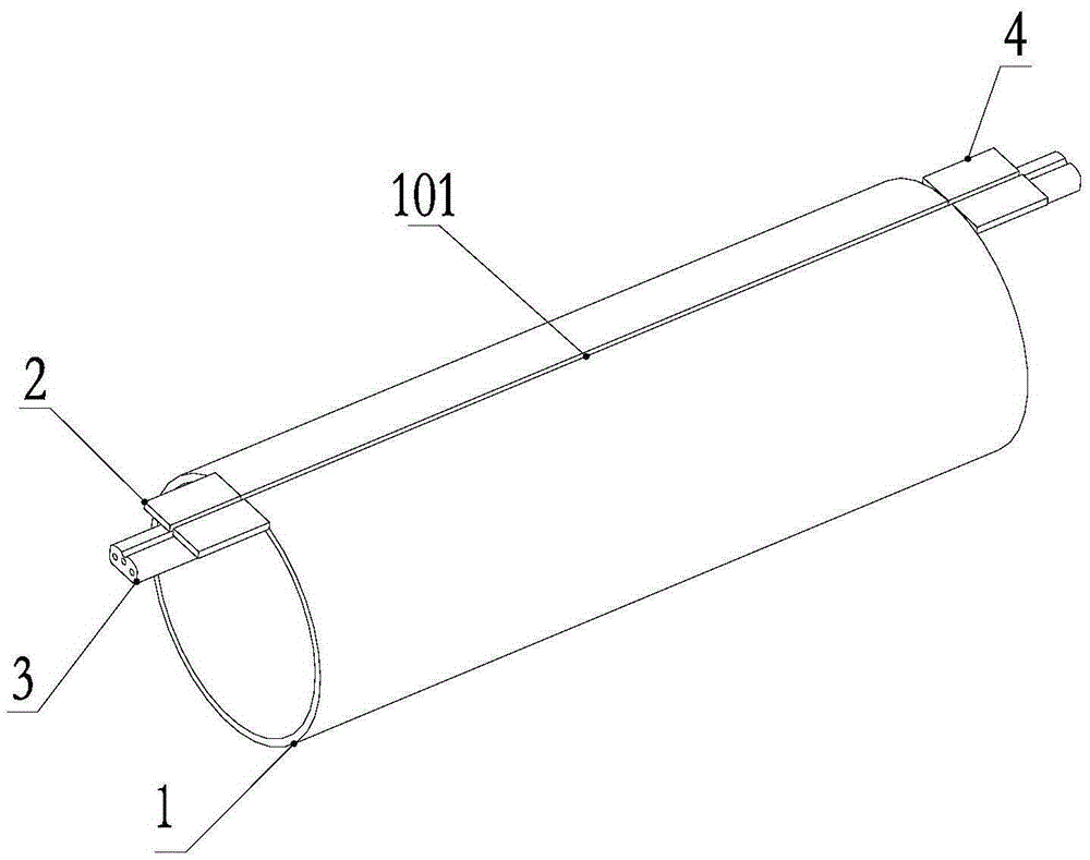
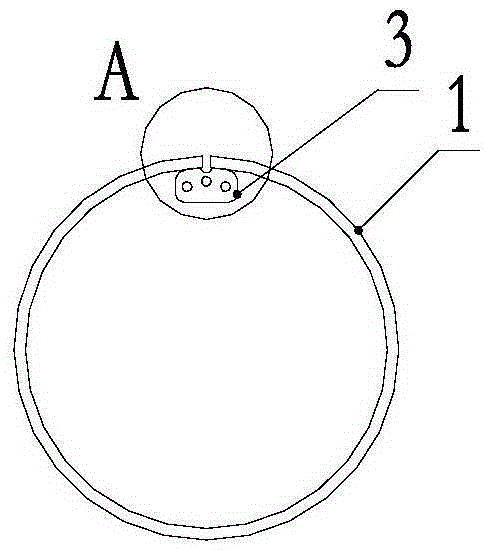
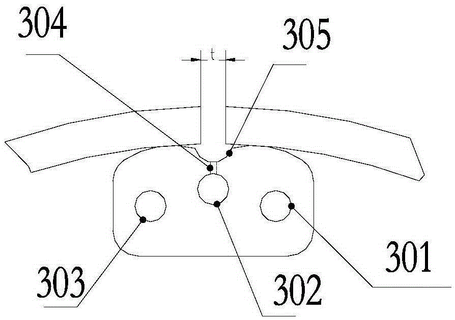
[0036] Such as Figure 1~3 As shown, the welding structure of this embodiment includes a copper strip 3, and the copper strip 3 is provided with a main air hole 302 and an air guide groove 305 along the length direction, and the main air hole 302 and the air guide groove 305 are arranged in parallel, and the main air hole 302 and the air guide groove 305 are arranged in parallel. A plurality of air guide holes 304 are arranged between the air grooves 305, and the two ends of the air guide holes 304 are respectively connected with the leading air holes 302 and the air guide grooves 305. The cross section of 101 is located in the same plane.

[0037] The diameter of the main air hole 302 is 10 mm, the diameter of the air guide hole 304 is 1.5 mm, and the diameter of the air guide groove 305 is 12 mm.

[0038] Copper bar 3 is provided with cooling water inlet hole 301 and cooling water outlet hole 303 along the length direction, and cooling water enters copper bar 3 from cooling...

Embodiment 2

[0057] like Figure 4 As shown, the arc-starting plate 2 and the arc-extinguishing plate 4 of this embodiment are both one piece, and the center lines of the arc-starting plate 2 and the arc-extinguishing plate 4 are on the same straight line as the longitudinal slit 101 .

[0058] Other implementations are the same as in Example 1.


PUM

PropertyMeasurementUnit
The way toaaaaaaaaaa

Abstract

The invention discloses a welding structure for an inner container longitudinal seam of a stainless steel gas cylinder and a welding method. The welding structure comprises a strip-shaped auxiliary board, wherein a main gas guide hole and a gas guide groove are formed in the strip-shaped auxiliary boar in the length direction; the main gas guide hole and the gas guide groove are arranged in parallel; a plurality of gas guide small holes are formed between the main gas guide hole and the gas guide groove; the two ends of the gas guide small holes are respectively communicated with the main gas guide hole and the gas guide groove; and the cross section of the gas guide groove and the cross section of the longitudinal seam to be welded are positioned in the same plane. The welding method comprises the following steps: rolling round; carrying out butt welding and spot welding; carrying out spot welding on run-on plates and run-off plates; clamping; and welding. According to the invention, an MIG automatic welding process is adopted, so that the primary input-cost of welding equipment is low; in a later using process, the input using and maintenance costs are relatively low and the working efficiency is improved greatly. By adopting the process in the invention, the qualification rate of nondestructive testing reaches 99.4% or above in an actual longitudinal seam welding process of an insulated gas cylinder and a cylinder for an LNG vehicle; and physical and chemical test projects completely meet standard requirements.

Description

technical field [0001] The invention relates to a welding process for the longitudinal seam of an inner tank of a heat-insulating gas cylinder and an LNG vehicle bottle, in particular to a welding structure and a welding method for a longitudinal seam of an inner tank of a stainless steel gas cylinder. Background technique [0002] Welded insulated gas cylinders and LNG vehicle cylinders (also called liquefied natural gas cylinders for vehicles) are mainly composed of an inner tank and an outer shell, with a vacuum interlayer between the inner tank and the outer shell. In order to improve the insulation effect of the gas cylinder, the vacuum interlayer requires vacuuming. The inner tank of the gas cylinder is used to store low-temperature medium and withstand the internal pressure generated by the vaporization of the low-temperature medium; it is composed of three parts: the front head assembly of the inner tank, the cylinder body of the inner tank and the rear head assembly...

Claims


Application Information

Patent Timeline
IPC IPC(8): B23K9/173B23K9/32B23K9/235B23K9/025B23K35/38B23K101/12B23K103/04
CPCB23K9/0253B23K9/164B23K9/173B23K9/235B23K9/323B23K9/325B23K35/383B23K2101/12B23K2103/04
Inventor 黄同福周其雷陈伟
Owner ANHUI DAPAN SPECIAL EQUIP VEHICLE CO LTD
Why Eureka
Try Eureka