Method for preparing micro-fluidic/milli-fluidic chip by using detachable template

A technology for dismantling templates and chips, applied in laboratory containers, chemical instruments and methods, laboratory utensils, etc., can solve the problems of prolonging chip preparation cycle, expensive equipment and cost, substrate falling off, etc., to achieve pipeline crossing The effect of large adjustable range of angle, less labor-consuming and adjustable size

Inactive Publication Date: 2016-01-27
LASER FUSION RES CENT CHINA ACAD OF ENG PHYSICS
View PDF5 Cites 3 Cited by
  • Summary
  • Abstract
  • Description
  • Claims
  • Application Information

AI Technical Summary

Problems solved by technology

However, the above-mentioned several methods, except the etching method, all need to prepare a mold with a microstructure at first, thus prolonging the preparation cycle of the chip; on the other hand, the above-mentioned methods including the etching method all need to cover chip-to-substrate bonding
For polymer materials, after long-term immersion in organic solvents, problems such as swelling will inevitably occur. Therefore, the substrates bonded by bonding will have problems such as shedding and leakage after long-term use.
The high-vacuum oxygen plasma sealing technology invented by Duffy et al. has realized the irreversible sealing of polydimethylsiloxane (polydimethylsiloxane, PDMS), but its expensive equipment and cost limit the application of this method.

Method used


Image

  • Method for preparing micro-fluidic/milli-fluidic chip by using detachable template

Examples


Embodiment 1

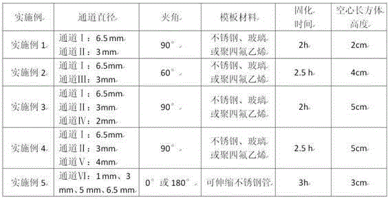
[0041] Example 1 is a T-shaped microchannel chip template made by using the method for preparing a micro / millifluidic chip using a detachable template of the present invention.

[0042] Place the cuboid-shaped glass sheet horizontally on the aluminum foil, fold the aluminum foil up along the sides of the glass sheet to wrap the four sides of the glass sheet, and wrap the glass sheet into a hollow cuboid with an upper opening to form a detachable mold prepolymer body container; pass the smooth surface stainless steel rod Ⅰ through the hollow cuboid along the long side of the hollow cuboid below the horizontal symmetrical centerline to form channel Ⅰ, pass one end of the smooth surface stainless steel rod Ⅱ through the aluminum foil of the hollow cuboid, and the other One end is bonded to the stainless steel rod Ⅰ, the adhesive is 502 glue or AB glue, so that the stainless steel rod Ⅱ and the stainless steel rod Ⅰ form an angle of 90°, the stainless steel rod Ⅱ forms a channel Ⅱ,...

Embodiment 2

[0046] Example 2 is a Y-shaped microchannel chip template made by using the method for preparing a micro / millifluidic chip using a detachable template of the present invention. Embodiment 2 is basically the same as Embodiment 1, the main difference being that the stainless steel rod II and the stainless steel rod I form an included angle of 60°, and the stainless steel rod II forms the channel III to form a Y-shaped channel template.

[0047] The specific parameters are shown in Table 1.

Embodiment 3

[0049] Example 3 is a cross-shaped microchannel chip template made by using the method for preparing a micro / millifluidic chip using a detachable template of the present invention. Embodiment 3 is basically the same as Embodiment 1. The main difference is that a stainless steel rod III symmetrical to the stainless steel rod II is added, and the stainless steel rod III forms an angle of 90° with the stainless steel rod I, and the stainless steel rod III forms a channel IV. Cross-shaped channel template.

[0050] The specific parameters are shown in Table 1.


PUM


Abstract

The invention provides a method for preparing a micro-fluidic / milli-fluidic chip by using a detachable template. The method comprises steps as follows: a, a detachable container is prepared; b, a pipeline is reserved, and the template is prepared; c, a prepolymer is poured and a die is solidified; d, an aluminum foil, a glass sheet and the template of the die are detached, and a micro-fluidic / milli-fluidic chip blank is obtained; e, the micro-fluidic / milli-fluidic chip blank is cut, and the micro-fluidic / milli-fluidic chip is obtained. The method has the characteristics that the processing technology is simple, controllability is high, and the stability of the obtained chip is good.

Description

technical field [0001] The invention belongs to the technical field of micro / millifluidic chip preparation, and in particular relates to a method for preparing a micro / millifluidic chip using a detachable template. Background technique [0002] Since the miniature total analysis system was first proposed by Manz and Widmer of Giba-Geigy in Switzerland in 1990, it has received extensive attention from various intersecting fields such as analytical chemistry, materials science, and biomedicine. Its core is the micro / millifluidic chip. preparation. At present, the materials widely used in chip preparation mainly include quartz, glass, silicon materials, and polymer materials. Quartz has good chemical inertness and surface stability, especially its excellent electroosmotic properties, and is favored by many researchers, but its disadvantages are that it is difficult to form channels with large aspect ratios, high material costs, and difficult bonding. Glass is widely used beca...

Claims


Application Information

Patent Timeline
Patent Type & Authority Applications(China)
IPC IPC(8): B01L3/00
Inventor 李泽甫罗炫王晓军张林杨怡
Owner LASER FUSION RES CENT CHINA ACAD OF ENG PHYSICS
Why Eureka
Try Eureka