Flip white-light LED device and manufacturing method thereof

A technology of LED devices and manufacturing methods, which is applied to semiconductor devices, electrical components, circuits, etc., and can solve reliability, light-emitting effect manufacturing costs and price obstacles, easy uneven coating of fluorescent materials, high temperature resistance, and air tightness Defects and other problems, to achieve the effect of large-scale integrated packaging, saving the amount of powder and glue, and good light output

Active Publication Date: 2016-01-27
APT ELECTRONICS
View PDF10 Cites 7 Cited by
  • Summary
  • Abstract
  • Description
  • Claims
  • Application Information

AI Technical Summary

Problems solved by technology

[0005] However, for this type of traditional packaging structure, due to the different thermal expansion coefficients of the bracket, the fluorescent glue on the LED chip, and the packaging glue, there are certain hidden dangers in the reliability of the package; moreover, for this packaging structure, the fluorescent material is easy to coat Uneven coverage and inconsistent thickness will lead to problems such as uneven white light color and color cast
[0006] In addition, in the existing market, LED brackets are mostly made of PPA, PCT or EMC materials, and these materials have major defects in high temperature resistance, air tightness, etc.
Although the ceramic bracket has good high temperature resistance and air tightness, the cost of the ceramic bracket is close to the cost of the chip, and because the side wall cannot be covered by phosphor powder, it is easy to leak blue light, and the manufacturing cost required for the ceramic bracket to package the LED is expensive. The investment in equipment is large, which leads to the small production capacity and high price of LED products with ceramic brackets
[0007] In other words, the shortcomings of traditional flip-chip white LED products in terms of reliability, light output effect, manufacturing cost and price have become a major obstacle to their replacement of traditional lighting products.

Method used


Image

  • Flip white-light LED device and manufacturing method thereof
  • Flip white-light LED device and manufacturing method thereof
  • Flip white-light LED device and manufacturing method thereof

Examples


Embodiment 1

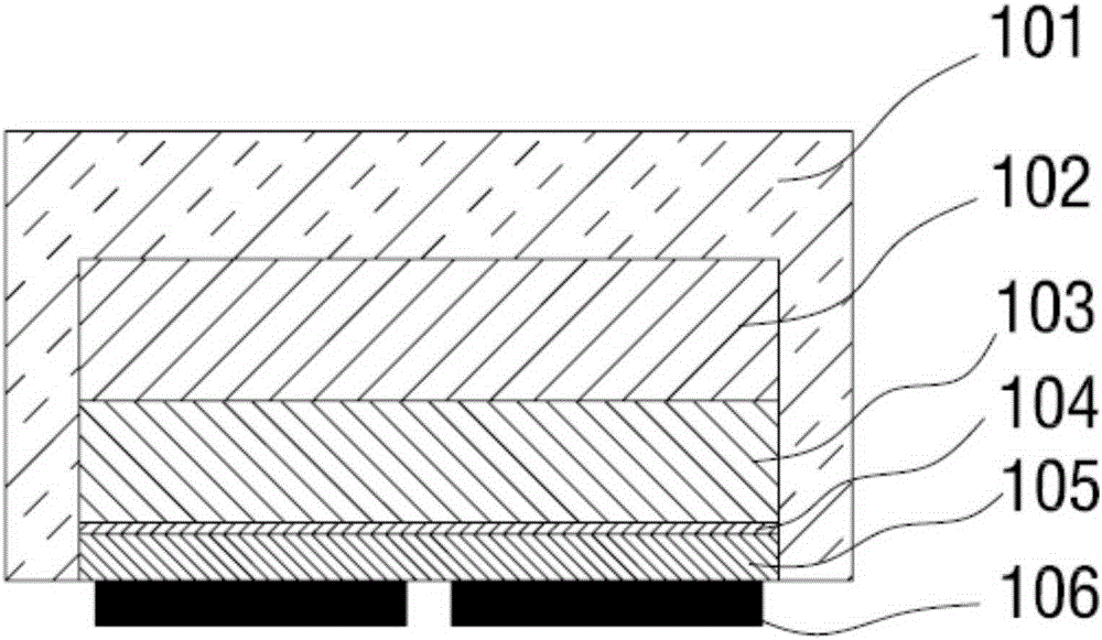
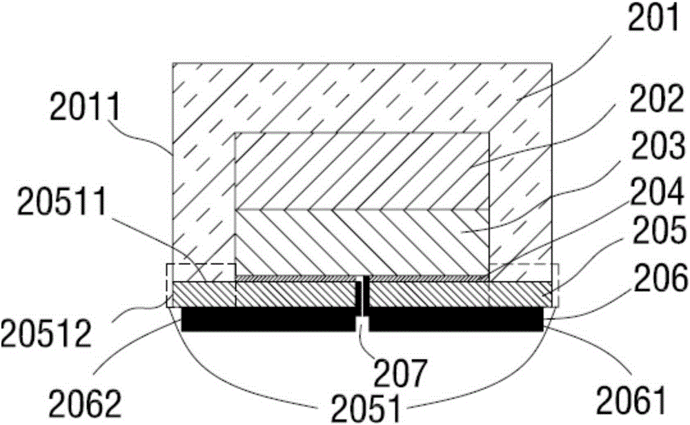
[0054] Such as figure 2 , Figure 3a As shown, this embodiment provides a flip-chip white LED device, the white LED device includes a wavelength conversion layer 201 and a light emitting unit 208, the light emitting unit 208 includes an epitaxial layer substrate 202, which is sequentially stacked and grown on the epitaxial layer substrate 202 The first semiconductor layer 203 , the active layer 204 , the second semiconductor layer 205 and the conventional electrode metal layer 206 , that is, the light emitting unit 208 have a flip-chip structure.

[0055] In particular, the second semiconductor layer 205 extends outward to form a protruding portion 2051 , so that the light emitting unit 208 has an inverted T structure.

[0056] In particular, the wavelength conversion layer 201 completely covers the epitaxial layer substrate 202, the first semiconductor layer 203, the active layer 204, up to the upper surface 20511 of the protrusion, and the wavelength conversion layer 201 d...

Embodiment 2

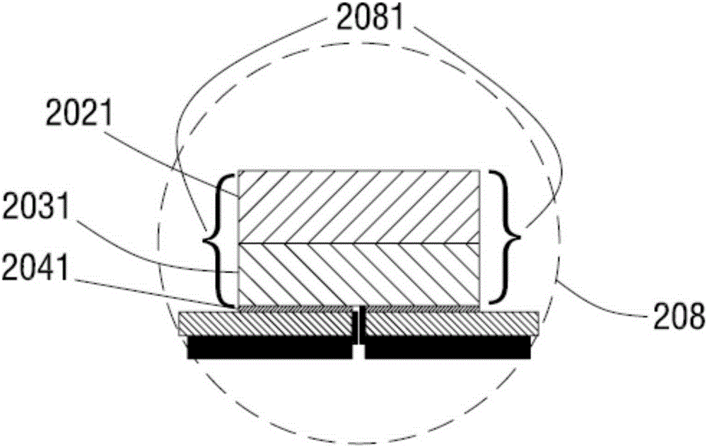
[0078] 1. A flip-chip white light LED device provided in this embodiment, such as Figure 4 As shown, the structural differences from Embodiment 1 are only: the third sidewall boundary 2021 on the epitaxial layer substrate 202, the fourth sidewall boundary 2031 on the first semiconductor layer 203, and the first sidewall boundary 2031 on the active layer 204. The sixth sidewall boundary 2081 formed by the five sidewall boundaries 2041 is inclined, so that the overall appearance of the light emitting unit 208 is trapezoidal.

[0079] Since the second side wall boundary 20512 of the protrusion 2051 is not covered by the wavelength conversion layer 201, there is a certain risk of blue light leakage. When the sixth side wall boundary 2081 is inclined, when the light with the first wavelength is reflected by the reflective layer and passes through the wavelength conversion layer 201, the probability of the light with the first wavelength passing through the side wall 20512 of the p...

Embodiment 3

[0084]1. A flip-chip white light LED device provided in this embodiment, such as Figure 5 As shown, the structural difference from Embodiment 2 is only that: the white LED device further includes a transparent adhesive layer 401 covering the wavelength conversion layer 201 .

[0085] Same as Embodiment 2, the sixth side wall boundary 2081 in this embodiment is also inclined, with an inclination angle 402 .

[0086] Wherein, the thickness of the wavelength conversion layer 201 ranges from 5 to 15 microns, so that the thickness of the wavelength conversion layer 201 is in a thinner and better range, so as to ensure that the white light LED device has better light color uniformity. However, the thickness of the wavelength conversion layer 201 is not limited to this thickness range, and the specific thickness is determined according to the needs of actual products.

[0087] 2. The manufacturing method of the flip-chip white LED device provided in this embodiment differs from Emb...


PUM


Abstract

The invention provides a flip white-light LED device and a manufacturing method thereof. The flip white-light LED device comprises a wavelength conversion layer and a light emitting unit, wherein the light emitting unit is of a flip-chip structure; a second semiconductor layer of the light emitting unit extends outwardly to form a projection part, so that the light emitting unit is of an inverted T structure; the wavelength conversion layer fully covers an epitaxial layer substrate, a first semiconductor layer and an active layer of the light emitting unit, and reaches the upper surface of the projection part without covering the second semiconductor layer and a conventional electrode metal layer of the light emitting unit; and a through hole is formed between the conventional electrode metal layer and the first semiconductor layer, the through hole only penetrates the conventional electrode metal layer, the second semiconductor layer and the active layer, is used for the electrical connection of a first electrode and the first semiconductor layer, and is used for the electrical connection of a second electrode and the second semiconductor layer. The flip white-light LED device provided by the invention is high in reliability and has good light emitting effect; and the manufacturing method of the flip white-light LED device is simple in steps, reduces production cost, and effectively increases productivity.

Description

technical field [0001] The invention belongs to the technical field of LEDs, and in particular relates to a flip-chip white light LED device and a manufacturing method thereof. Background technique [0002] A light emitting diode (LED) is a semiconductor device that is excited to generate light of various colors in response to an electric current, and has the advantages of high efficiency, long life, and no harmful substances such as Hg. With the rapid development of LED technology, the brightness and lifespan of LEDs have been greatly improved, making the application of LEDs more and more extensive. From outdoor lighting such as street lights to urban lighting such as decorative lights, they are all used or Replace with LED as light source. [0003] In the semiconductor lighting industry, the structure of LED chips is generally divided into three types: front chip structure, vertical chip structure and flip chip structure. Compared with the other two chip structures, the ...

Claims


Application Information

Patent Timeline
Patent Type & Authority Applications(China)
IPC IPC(8): H01L33/48H01L33/50H01L33/64H01L33/00
CPCH01L33/005H01L33/486H01L33/505H01L33/64H01L2933/0033H01L2933/0041H01L2933/0075
Inventor 吴金明肖国伟姜志荣万垂铭曾照明
Owner APT ELECTRONICS
Why Eureka
Try Eureka