Turbofan type vehicle engine

An automobile engine and engine technology, applied in the direction of machines/engines, jet propulsion devices, etc., can solve the problems of high fuel consumption, unable to completely improve the quality of the engine, etc., and achieve the effect of high output power, small mass, and large thrust-to-weight ratio

Inactive Publication Date: 2016-02-03
丁义存
View PDF6 Cites 5 Cited by
  • Summary
  • Abstract
  • Description
  • Claims
  • Application Information

AI Technical Summary

Problems solved by technology

However, only changing its air intake method cannot completely improve the shortcomings of the engine, such as large mass, high fuel consumption, and poor power.

Method used


Image

  • Turbofan type vehicle engine
  • Turbofan type vehicle engine
  • Turbofan type vehicle engine

Examples


Embodiment 1

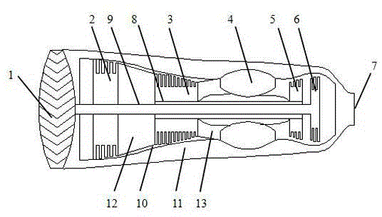
[0020] Such as figure 1 Shown, the turbofan automobile engine of the present invention mainly comprises fan 1, low-pressure compressor 2, high-pressure compressor 3, combustion chamber 4, high-pressure turbine 5, low-pressure turbine 6, nozzle 7, high-pressure shaft 8, low-pressure shaft 9. Inner channel 10 and outer channel 11 are formed. The inner duct 10 is supported in the outer duct 11 by a front bracket and a rear bracket, the high-pressure shaft 8 and the low-pressure shaft 9 are respectively supported in the inner duct 10 by a front bearing and a rear bearing, and the high-pressure shaft 8 is hollow, The low-pressure shaft 9 passes through the high-pressure shaft 8, the fan 1, the low-pressure compressor 2, and the low-pressure turbine 6 are mounted on the low-pressure shaft 9 through a one-way bearing, and the high-pressure compressor 3 and high-pressure turbine 5 are mounted on the high-pressure shaft 8 through a one-way bearing Above, the fan 1, the low-pressure c...

Embodiment 2

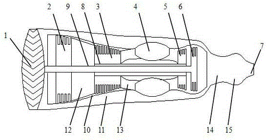
[0057] In order to increase the instantaneous thrust of the turbofan automobile engine, an exhaust gas mixing chamber 14 and an afterburner 15 are also arranged between the low-pressure turbine 6 and the nozzle 7, such as figure 2 shown. When the gas enters the exhaust mixing chamber 14 through the outer duct 11 and the inner duct 10, the gas is mixed in the exhaust mixing chamber 14, and the afterburner 15 continues to inject fuel into the airflow to further accelerate the airflow to increase the driving force , the airflow passing through the bypass duct 11 is about one-third of the airflow passing through the engine. The exhaust mixing chamber 14 is composed of a rectification cross plate, a rectification support plate, a rectification cone and an outer wall. The rectification support plate is used to eliminate the vortex of the gas passing through the low-pressure turbine 6. Ten oblique funnel-type windows on the outer wall make the outer duct The gas of 11 is effectivel...

Embodiment 3

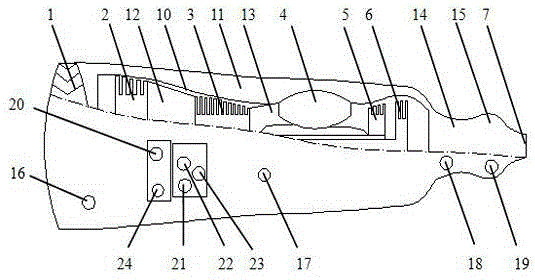
[0064] Correspondingly, nine accessory systems are also arranged on the turbofan automobile engine, and the accessory systems are installed on the two gearboxes at the bottom of the engine, such as image 3 shown. The two gearboxes are divided into a high-speed gearbox and a low-speed gearbox. The high-speed gearbox is located at the end of the intermediate casing 12 close to the high-pressure compressor 3 and is driven by the power output by the high-pressure rotor. The low-pressure gearbox is located at the intermediate casing. 12 Close to the end of the low-pressure compressor 2, driven by the output power of the low-pressure rotor, the accessory system mainly includes the following nine parts: the lubricating oil cleaning system 16, which mainly consists of engine lubricating oil tank, pressure oiling nozzle, lubricating oil filter, magnetic chip detection Oil cooler, lubricating oil pump, air-cooled lubricating oil radiator, fuel-cooled lubricating oil radiator, constant ...


PUM


Abstract

The invention discloses a turbofan type vehicle engine. The turbofan type vehicle engine mainly consists of a fan, a low-pressure compressor, a high-pressure compressor, a combustion chamber, a high-pressure turbine, a low-pressure turbine, a spraying pipe, a high-pressure shaft, a low-pressure shaft, an inner duct and an outer duct, wherein the inner duct is supported on the outer duct through a front bracket and a back bracket; the high-pressure shaft and the low-pressure shaft are respectively supported in the inner duct through a front bearing and a back bearing; the high-pressure shaft is hollowed; the low-pressure shaft penetrates through the high-pressure shaft; the fan, the low-pressure compressor and the low-pressure turbine are mounted on the low-pressure shaft through a one-way bearing; and the high-pressure compressor and the high-pressure turbine are mounted on the high-pressure shaft through a one-way bearing. The turbofan type vehicle engine has such advantages as light mass, high output power, strong power and high thrust-weight ratio, and in particular, is suitable for such vehicles having higher requirements on speed as sports cars.

Description

technical field [0001] The invention relates to the technical field of engines, in particular to a turbofan automobile engine. Background technique [0002] Most of the engines currently used in automobiles are reciprocating piston internal combustion engines, which have the disadvantages of high fuel consumption, poor power, and environmental protection. In order to increase the power of the engine, people think of improving the air intake method of the intake system, that is, using a supercharger to increase the intake pressure, increase the intake air density, and increase the power of the internal combustion engine, thereby increasing the output power of the engine. However, just changing its air intake method cannot completely improve the shortcomings of the engine, such as high mass, high fuel consumption, and poor power. [0003] Therefore, in order to overcome the shortcoming that exists in the prior art, be badly in need of a kind of novel automobile engine that ma...

Claims


Application Information

Patent Timeline
Patent Type & Authority Applications(China)
IPC IPC(8): F02K3/00
Inventor 丁义存
Owner 丁义存
Why Eureka
Try Eureka